Cylindrical workpiece outer circle machining clamp and using method thereof

A workpiece and cylindrical technology, which is applied in the field of cylindrical workpiece cylindrical processing fixtures, can solve problems such as uneven force, and achieve the effects of enhanced clamping effect, uniform force, and improved processing accuracy

Inactive Publication Date: 2014-12-10
NANTONG INST OF TECH
View PDF7 Cites 19 Cited by
  • Summary
  • Abstract
  • Description
  • Claims
  • Application Information

AI Technical Summary

Problems solved by technology

[0006] In order to solve the problem of uneven stress on the two ends and the middle part of the existing fixture, the present invention provides a cylindrical workpiece cylindrical processing fixture. During turning, the force is uniform, and the parts will not be deformed and the accuracy will not be reduced due to the influence of clamping force and cutting force.

Method used


Image

  • Cylindrical workpiece outer circle machining clamp and using method thereof
  • Cylindrical workpiece outer circle machining clamp and using method thereof
  • Cylindrical workpiece outer circle machining clamp and using method thereof

Examples


Embodiment 1

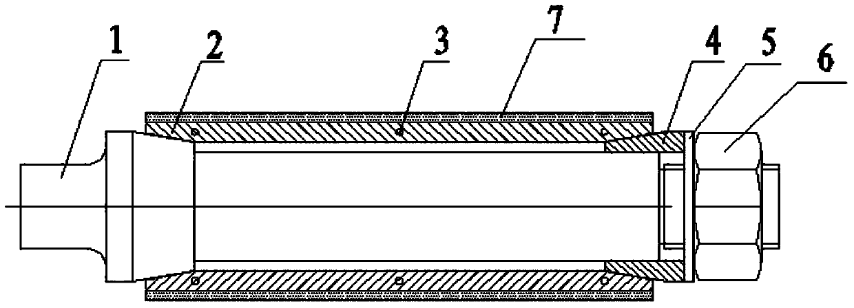
[0029] Such as figure 1 As shown, a cylindrical workpiece external machining fixture provided by the present invention mainly includes a fixed core 1, an expansion sleeve 2, a movable core 4, a gasket 5, and a lock nut 6, the expansion sleeve 2, the movable core 4 , The gasket 5 is sleeved on the fixed core 1, the expansion sleeve 2 is located between one end of the fixed core 1 and the movable core 4, and the lock nut 6 is located at the other end of the fixed core 1. . The expansion sleeve 2 is composed of multiple identical expansion strips, and each expansion strip has a concentric inner arc surface and an outer arc surface.

Embodiment 2

[0031] Such as figure 1 As shown, a cylindrical workpiece external machining fixture provided by the present invention mainly includes a fixed core 1, an expansion sleeve 2, a movable core 4, a gasket 5, and a lock nut 6, the expansion sleeve 2, the movable core 4 , The gasket 5 is sleeved on the fixed core 1, the expansion sleeve 2 is located between one end of the fixed core 1 and the movable core 4, and the lock nut 6 is located at the other end of the fixed core 1. . The expansion sleeve 2 is composed of multiple identical expansion strips, and each expansion strip has a concentric inner arc surface and an outer arc surface.

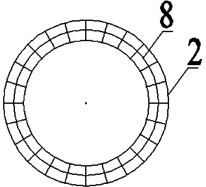
[0032] Such as figure 2 , As shown in 3, the expansion sleeve 2 is a cylindrical structure composed of 24 identical expansion strips. Each expansion strip of the expansion sleeve 2 has a through hole 3 in the middle and both ends. The 24 identical expansion strips An elastic rubber cord 8 passes through the through holes between the same parts of the ...

Embodiment 3

[0035] Such as figure 1 As shown, a cylindrical workpiece external machining fixture provided by the present invention mainly includes a fixed core 1, an expansion sleeve 2, a movable core 4, a gasket 5, and a lock nut 6, the expansion sleeve 2, the movable core 4 , The gasket 5 is sleeved on the fixed core 1, the expansion sleeve 2 is located between one end of the fixed core 1 and the movable core 4, and the lock nut 6 is located at the other end of the fixed core 1. . The expansion sleeve 2 is composed of multiple identical expansion strips, and each expansion strip has a concentric inner arc surface and an outer arc surface.

[0036] The circular washer 5 is located between the movable core and the lock nut.

[0037] The expansion sleeve 2 has a cylindrical shape, and both ends of the expansion sleeve 2 are both inner cone structures. One end of the fixed core 1 has an optical axis structure, the fixed core 1 close to the optical axis structure has an outer cone structure, th...


PUM


Abstract

The invention relates to a cylindrical workpiece outer circle machining clamp and a using method thereof. The cylindrical workpiece outer circle machining clamp mainly comprises a fixed core, an expansion sleeve, a movable core, a gasket and a locking nut. The using method of the machining clamp is that the locking nut is rotated to push the movable core to move so as to squeeze the expansion sleeve, the expansion sleeve expands outwards in the radial direction under the combined action of a conical face of the fixed core and a conical face of the movable core, and therefore a cylindrical workpiece is clamped. Compared with an elastic clamp in the prior art, the dual-directional conical face expansion type design is adopted by the cylindrical workpiece outer circle machining clamp, in the expansion process, the overall expansion sleeve expands outwards to enable a machined workpiece to be evenly stressed, the clamping effect of the clamp is enhanced, and machining precision is greatly improved.

Description

Technical field [0001] The invention relates to the technical field of mechanical processing, in particular to a fixture for machining the outer circle of a cylindrical workpiece. technical background [0002] Due to poor rigidity and weak strength, thin-walled cylinder parts are easily affected by clamping force and cutting force during processing, and are extremely easy to deform, thereby affecting the dimensional accuracy, position accuracy and surface roughness of the parts. [0003] The current lathe fixtures are usually clamped with three-jaw or four-jaw chucks during turning. However, in order to reduce the impact of the clamping force on the thin-walled kit, the following measures are generally adopted in the turning process: 1) Change the jaws It is a soft metal material and the contact surface is enlarged. With special soft jaws to clamp the workpiece, the clamping force is evenly distributed on the larger contact surface, and the workpiece will not be deformed. However,...

Claims


Application Information

Patent Timeline
Patent Type & Authority Applications(China)
IPC IPC(8): B23B31/40
CPCB23B31/4066
Inventor 顾海孙健华顾拥军袁国定胡美云周修鹏
Owner NANTONG INST OF TECH
Why Eureka
Try Eureka