Building component self-pressurization expansion type pore-forming die

An expansion technology for building components, applied in the direction of molds, etc., can solve the problems of high labor intensity, complicated operation, and difficult to guarantee the quality of holes, so as to avoid the inability to demould, reduce the number of workers, and ensure the quality of holes.

Active Publication Date: 2014-12-10
苏州盛泽科技创业园发展有限公司
View PDF3 Cites 2 Cited by
  • Summary
  • Abstract
  • Description
  • Claims
  • Application Information

AI Technical Summary

Problems solved by technology

The disadvantage of this method of forming holes is that: in the process of making prefabricated parts, it is necessary to manually rotate or twitch the mold one by one, which takes up a lot of human resources, the labor intensity of the workers is high, and the production efficiency is low; the degree of solidification of the prefabricated materials needs to be accurately grasped. If the timing is not grasped, it is easy to cause damage to the solidified material, making it difficult to guarantee the quality of the hole. If the manual operation is not timely, the mold will not be able to be demoulded.
However, although these disclosed methods have certain advantages, they are complex in structure and complex in operation, which still cannot solve the above problems, and have not been applied in industrialized production so far.

Method used


Image

  • Building component self-pressurization expansion type pore-forming die
  • Building component self-pressurization expansion type pore-forming die
  • Building component self-pressurization expansion type pore-forming die

Examples


Embodiment Construction

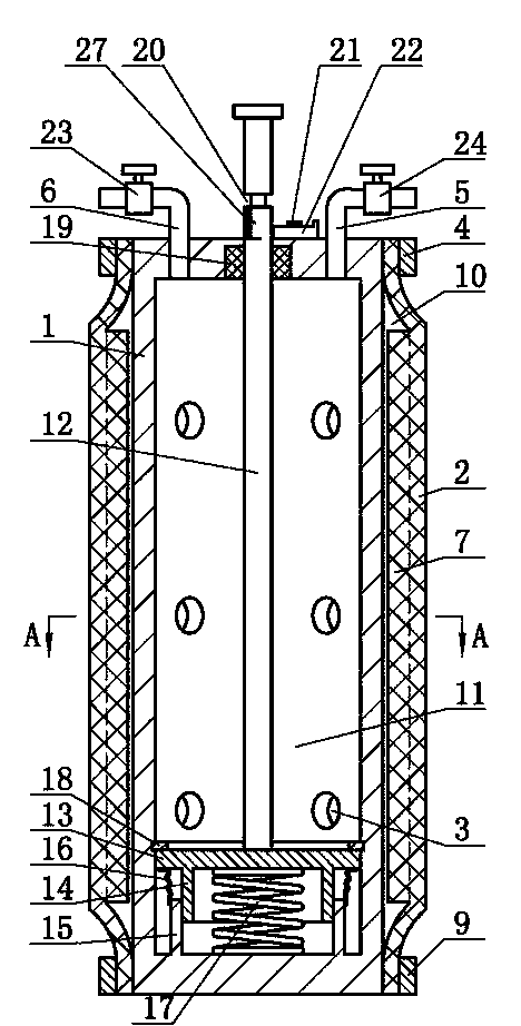
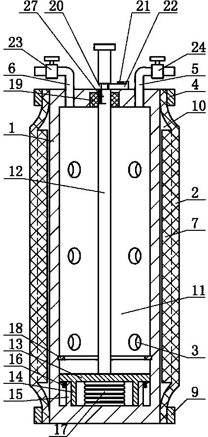
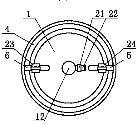
[0011] The building component self-pressurization expansion type hole-forming mold of the present invention includes a hard shell 1, the interior of the hard shell 1 is a cavity 11, and a soft cover 2 is installed around the side wall of the hard shell 1, and the soft cover 2 The two ends are respectively connected to the hard shell 1 through the first clamp 4 and the second clamp 9, an expansion chamber 10 is formed between the inner wall of the soft cover 2 and the outer wall of the hard shell 1, and a through hole is set on the side wall of the hard shell 1 3. The cavity 11 communicates with the expansion cavity 10 through the through hole 3, the piston 13 is installed in the cavity 11, one side of the piston 13 is connected with the inner sleeve 14, and the outer sleeve 15 is arranged outside the inner sleeve 14, and the outer sleeve 15 is connected with the hard The shell 1 is connected, the spring 17 is installed between the piston 13 and the hard shell 1, the other side ...


PUM


Abstract

A building component self-pressurization expansion type pore-forming die comprises a hard shell. A cavity is formed in the hard shell, a soft sleeve is arranged on the periphery of the side wall of the hard shell, the two ends of the soft sleeve are connected with the hard shell through a first hoop and a second hoop respectively, an expansion cavity is formed between the inner wall of the soft sleeve and the outer wall of the hard shell, through holes are formed in the side wall of the hard shell, the cavity is communicated with the expansion cavity through the through holes, and a piston is arranged in the cavity. One side of the piston is connected with an inner sleeve pipe, an outer sleeve pipe is arranged outside the inner sleeve pipe, the outer sleeve pipe is connected with the hard shell, a spring is arranged between the piston and the hard shell, the other side of the piston is connected with one end of a push rod, and the other end of the push rod penetrates out of the top of the hard shell. Accordingly, technicians in the field provide multiple schemes to solve the problems, however, even though public methods have some advantages, the public methods can not solve the problems.

Description

technical field [0001] The invention relates to a hole-forming die for building components, in particular to a self-pressurizing and expanding hole-forming die for building components. Background technique [0002] Prefabricated elements manufactured in the construction sector have many structures with holes. When making prefabricated components, metal materials are generally used as hole molds for the formation of holes. When the concrete is solidified to a certain strength, the hole mold needs to be manually rotated or twitched to separate the hole mold from the concrete, which is convenient for smooth demoulding. When the strength reaches a higher level, the hole die is pulled out. The disadvantage of this method of forming holes is that: in the process of making prefabricated parts, it is necessary to manually rotate or twitch the mold one by one, which takes up a lot of human resources, the labor intensity of the workers is high, and the production efficiency is low; t...

Claims


Application Information

Patent Timeline
Patent Type & Authority Applications(China)
IPC IPC(8): B28B7/22B28B7/16
CPCB28B7/16B28B7/22
Inventor 苑希平
Owner 苏州盛泽科技创业园发展有限公司
Why Eureka
Try Eureka