
accelerator brake

A braking device and accelerator technology, applied in the field of accelerator braking devices, can solve the problems of unstable braking, long electromagnet energization time, short braking time, etc., and achieve the effects of stable braking, slow car speed, and prolonged braking time

Inactive Publication Date: 2016-08-24
朱荣根
View PDF7 Cites 0 Cited by
  • Summary
  • Abstract
  • Description
  • Claims
  • Application Information

AI Technical Summary

Problems solved by technology

[0003] The purpose of the present invention is to provide an accelerator brake device, which solves the technical defects of long electromagnet energization time, short braking time and unstable braking in the prior art

Method used


Image

  • accelerator brake
  • accelerator brake
  • accelerator brake

Examples


Embodiment Construction

[0025] The specific embodiments of the present invention will be further described below in conjunction with the accompanying drawings.

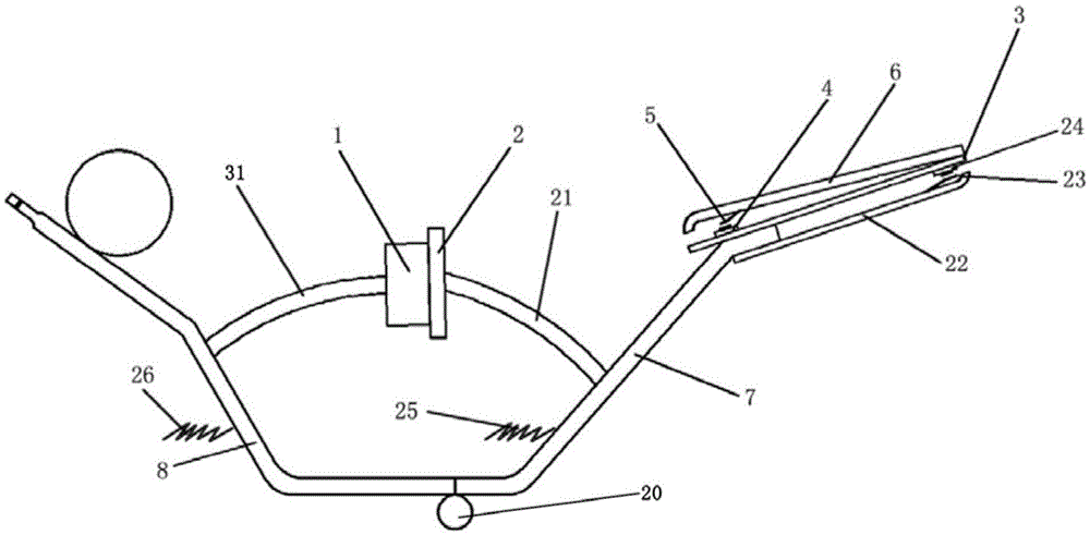
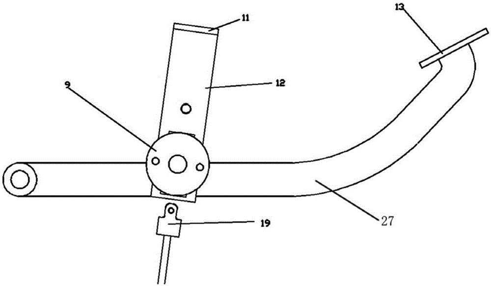
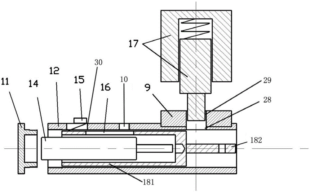
[0026] Such as Figure 1 to Figure 3 The gas brake device shown includes a throttle device and a brake device.

[0027] Such as figure 1 As shown, the throttle device includes a zigzag first throttle lever 7, a zigzag second throttle lever 8 and a rotating shaft 20 arranged on the vehicle body (not shown in the figure), one end of the first throttle lever 7 And one end of the second throttle lever 8 is rotated on the rotating shaft 20, the other end of the first throttle lever 7 and the other end of the second throttle lever 8 are respectively located on both sides of the rotating shaft 20, and the middle part of the first throttle lever 7 is provided with a first Fixed rod 21, the free end of the first fixed rod 21 is provided with iron sheet 2, the middle part of the second throttle lever 8 is provided with second fixed rod 31, and the f...


PUM


Abstract

The invention discloses an accelerator brake device, comprising an accelerator device and a brake device; the accelerator device includes a first throttle lever, a second throttle lever, a rotating shaft, a first fixed rod, a second fixed rod, a first electromagnet, an iron sheet, The return spring and the auxiliary spring, the brake device includes a brake lever installed on the car body with one end rotating, a guide cylinder fixed on the brake lever, a push rod arranged in the guide cylinder and can move axially along the guide cylinder, and a brake vacuum booster The ejector rod, the gas spring arranged in the guide cylinder to push the push rod to move, the second electromagnet arranged outside the guide cylinder, the first through hole is opened on the wall of the guide cylinder away from the gas spring, the shell of the second electromagnet Fixed on the guide cylinder, the iron core of the second electromagnet can expand and contract in the first through hole. The beneficial effect of the invention is that the braking time is prolonged, the speed of the car is slowly decreased, the braking is relatively stable, and the brake can be used as an emergency brake for accidentally stepping on the gas pedal or as a short-term parking brake.

Description

technical field [0001] The invention relates to an accelerator brake device, which belongs to the field of automobile manufacturing. Background technique [0002] As the price of cars is getting lower and lower, more and more people can afford cars, so more and more people learn to drive cars, and many people drive on the road as soon as they get their driver's licenses. Because novice drivers are unskilled, it is easy to use the accelerator as a brake, resulting in vehicle collisions, casualties and other traffic accidents. When the accelerator is used as the brake, various serious traffic accidents are caused. The gas brake device of an existing automobile is connected by an electromagnet and a brake vacuum booster. After stepping on the brake pedal, the electromagnet powers off and resets the brake. Since the power-on time of the electromagnet cannot be too long, the automatic reset time is relatively short, and people may still The brake has been reset before waking up...

Claims


Application Information

Patent Timeline
Patent Type & Authority Patents(China)
IPC IPC(8): B60K26/02B60T7/06
Inventor 朱荣根朱正丰
Owner 朱荣根
Learn More