Multifunctional ship with container positioning guide rail mechanisms

A technology for positioning guide rails and containers, which is used in ship accessories, transportation and packaging, load handling devices, etc., and can solve problems such as affecting the fixing effect of containers, easy displacement of containers, and damage to bulkhead rails.

Active Publication Date: 2014-12-10
ZHEJIANG OCEAN UNIV
View PDF9 Cites 2 Cited by
  • Summary
  • Abstract
  • Description
  • Claims
  • Application Information

AI Technical Summary

Problems solved by technology

[0003] The purpose of the present invention is to solve the problem that the container of the multipurpose ship in the prior art is easy to shift, which affects the fixing effect of the container or causes damage to the bulkhead track, and provides a multipurpose ship that can conveniently fix the conta

Method used


Image

  • Multifunctional ship with container positioning guide rail mechanisms
  • Multifunctional ship with container positioning guide rail mechanisms
  • Multifunctional ship with container positioning guide rail mechanisms

Examples


Embodiment 1

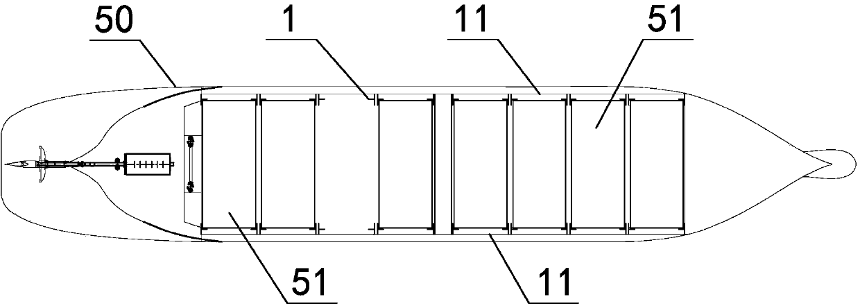
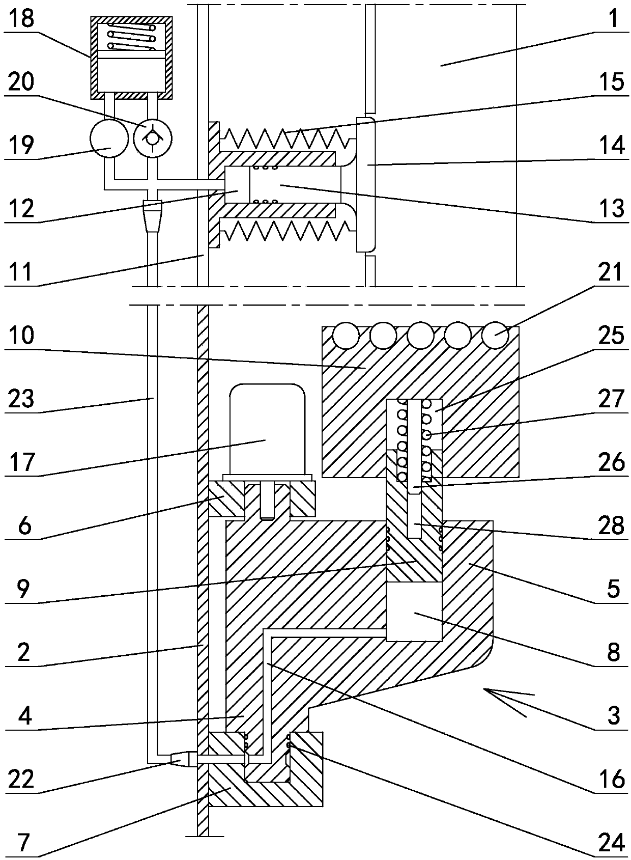
[0037] existfigure 1 In the shown embodiment 1, a multi-purpose ship 50 with a container positioning guide rail mechanism, eight sets of container positioning guide rail mechanisms are arranged in the cabin of the multi-purpose ship, and each set of container positioning guide rail mechanisms includes four sets of container positioning guide rail mechanisms fixed on The strip-shaped guide rail frame 2 on the bulkhead and perpendicular to the bottom plate of the cabin (see figure 2 ), the container positioning guide rail 1 with an L-shaped cross-section is fixed on the side of the guide rail frame away from the bulkhead and parallel to the guide rail frame, and a corbel support 3 is provided on the same height of the guide rail frame (see image 3 ), the corbel support includes a pivot shaft 4 parallel to the guide rail frame and a support body 5 arranged on one side of the pivot shaft, and the upper and lower ends of the pivot shaft are respectively connected to the upper pivo...

Embodiment 2

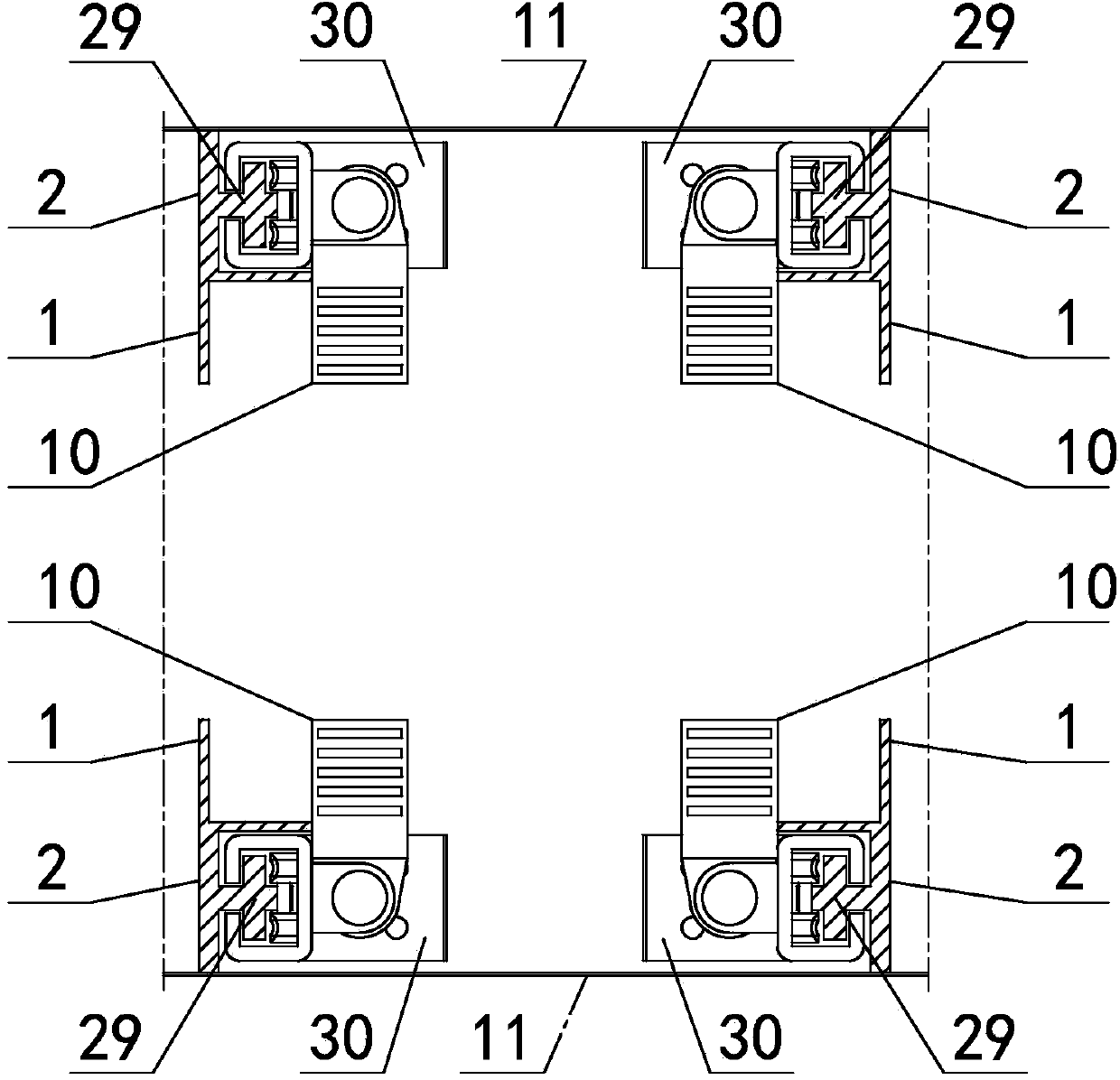
[0040] The corbel support of embodiment 2 is arranged on the guide rail frame by synchronous lifting mechanism (see Figure 7 ), the lifting mechanism includes a corbel support lifting guide rail 29 arranged on the guide rail frame and parallel to the guide rail frame and a corbel support drive box 30 arranged on the corbel support lift guide rail, and the corbel support drive box is L-shaped as a whole , the cross-section of the corbel support lifting guide rail is cross-shaped (see Figure 12 , Figure 13 ), including the fixed plate 31 and the limit strips 32 symmetrically arranged on both sides of the fixed plate, one side of the fixed plate is fixed on the rail frame between the container positioning guide rail and the bulkhead, and the other side of the fixed plate is set There are tooth grooves 33, and the limit chute 34 is formed between the limit strips on both sides of the fixed plate, the fixed plate and the guide rail frame; the corbel support drive box includes a...

Embodiment 3

[0044] The inboard of the container positioning guide rail of embodiment 3 is provided with guide slide (see Figure 10 ), the guide slide plate is composed of 2-4 guide assemblies sequentially connected, and in this embodiment there are 3 (see Figure 8 ), the cross-section of the guide assembly is L-shaped, and is composed of a left slide plate 44 and a right slide plate 45 that are respectively slidingly matched with the two inner surfaces of the container positioning guide rail. A roller groove perpendicular to the container positioning guide rail. Rollers are arranged in the roller groove. The outer edges of the left slide plate and the right slide plate are bent to form a positioning groove 46 adapted to the outer edge of the container positioning guide rail. Two adjacent guide assemblies The slide plates close to the bulkhead are hinged to each other. The lower ends of the left slide plate and the right slide plate of the guide assembly located at the lowermost end of t...


PUM


Abstract

The invention discloses a multifunctional ship with container positioning guide rail mechanisms. Every container positioning guide rail mechanism comprises four long-strip-shaped guide rail frames fixed to a cabin wall and perpendicular to a cabin bottom plate, bracket supports are arranged on the guide rail frames respectively at the same height, each bracket support comprises a pivot shaft parallel to the corresponding guide rail frame and a support body located on one side of the pivot shaft, an upper pivot base and a lower pivot base connected through the pivot shafts are connected with the guide rail frames, the inside of each support body is provided with a lower oil cylinder with the axis parallel to the corresponding guide rail frame, and the upper end of each lower oil cylinder piston is connected with a supporting block; the cabin wall above the bracket supports is provided with an upper oil cylinder with the axis perpendicular to the cabin wall face, the outer end of an upper oil cylinder piston is connected with an ejection block, a torsion spring is arranged between the ejection block and the upper oil cylinder, and the bottoms of the lower oil cylinders are communicated with the upper oil cylinder through hydraulic pipelines. The multifunctional ship effectively solves the problem that containers of existing multifunctional ships are likely to move and accordingly the container positioning effect is influenced or a cabin wall rail is damaged, and has high practical value.

Description

technical field [0001] The invention relates to the technical field of shipbuilding, in particular to a multipurpose ship with a container positioning guide rail mechanism. Background technique [0002] The bulkhead track on the multi-purpose ship is used to fix the relative position of the container. The four corners of the container are limited by the track composed of four angle steels to prevent the container from moving in the cabin; when the multi-purpose ship needs to transport dense cargo For example, when goods such as steel products, steel plates, and steel coils, these bulky goods can only be placed at the bottom of the cabin. After the cargo at the bottom of the cabin is placed, the container is placed overhead on the bulkhead track of the multi-purpose ship by using the support of four contoured corbels set on the four bulkhead tracks. The large space is used to load steel, steel plates, steel coils and other goods. Above these goods is a layer of containers, ...

Claims


Application Information

Patent Timeline
IPC IPC(8): B63B25/22B63B25/00
Inventor 陈正寿孙孟
Owner ZHEJIANG OCEAN UNIV
Why Eureka
Try Eureka