
Self-propelled self-elevating wind power transportation and installation vessel and installation method of wind turbines

A wind turbine, self-elevating technology, applied in the field of marine engineering, can solve problems such as increasing the lifting capacity of the crane, affecting the installation of the wind turbine, and deformation of the boom, so as to improve the safety factor of the equipment, reduce the additional dynamic load, and accurately install Effect

Inactive Publication Date: 2016-06-29
CHINA UNIV OF PETROLEUM (EAST CHINA)
View PDF6 Cites 0 Cited by
  • Summary
  • Abstract
  • Description
  • Claims
  • Application Information

AI Technical Summary

Problems solved by technology

[0004] The installation of offshore wind turbines requires high installation accuracy, but many factors will affect the installation of wind turbines
On the one hand, the installation location of the offshore wind turbine has a relatively large positioning wind speed, and the pulsating wind load acting on the wind turbine during the hoisting process will cause the wind turbine to sway; on the other hand, the traditional installation ship is equipped with a jib crane, and the crane The boom has greater flexibility, and the installation of offshore wind turbines has a trend of deeper water and higher power units, which will increase the lifting capacity of the crane and cause greater deformation of the boom

Method used


Image

  • Self-propelled self-elevating wind power transportation and installation vessel and installation method of wind turbines
  • Self-propelled self-elevating wind power transportation and installation vessel and installation method of wind turbines
  • Self-propelled self-elevating wind power transportation and installation vessel and installation method of wind turbines

Examples


Embodiment Construction

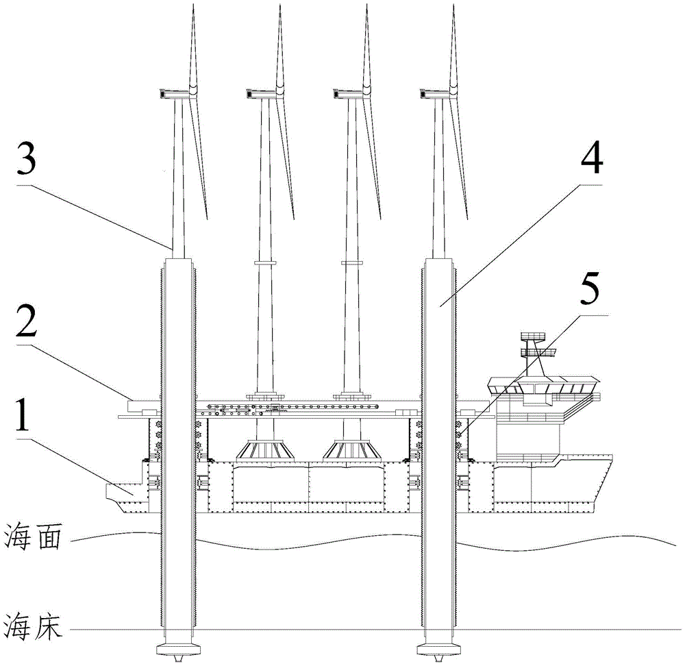
[0043] Such as figure 1 As shown, the self-propelled self-elevating wind power transportation and installation ship includes: hull 1, cantilever beam 2, pile leg 4, and rack and pinion lifting system 5; among them,

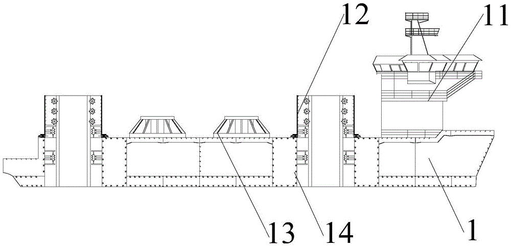
[0044] Hull 1 adopts double bottom and longitudinal frame structure, such as figure 2 , image 3 As shown; the bow is the living area 11 to meet the daily living, dining, entertainment, medical and other needs of the crew; four propellers are arranged on the stern, and one propeller on both sides of the ship; the stern thruster is used to transport wind turbines on the ship 3 During the process, the ship is provided with power, and the distance between the hull and the offshore wind turbine installation base 6 is adjusted through the stern thruster; after the self-propelled self-elevating wind power transport installation ship sails to the designated installation position, it passes through the propellers on the left and right sides of the ship Adjust the direction o...


PUM


Abstract

The invention belongs to the field of marine engineering, and in particular relates to a self-propelled self-elevating wind power transport and installation ship. The self-propelled self-elevating wind power transportation and installation ship includes: hull, cantilever beam, pile legs, and rack and pinion lifting system; multiple fixed bases for wind turbines are arranged on the hull deck along the longitudinal central axis; four are arranged on the left and right sides of the hull Well, the pile-fixing frame is installed above the well; pile legs are arranged in the well, and the legs extend downward through the pile-fixing frame and the well; racks are arranged on the front and rear sides of the pile body; the cantilever beam is fixed on the two sides On the pile fixing frame, the cantilever beam is equipped with a longitudinal sliding device, which includes a longitudinal sliding base and a longitudinal sliding guide rail; four sets of horizontal sliding devices are installed in parallel between the two longitudinal sliding guide rails, and each group of horizontal sliding devices The sliding device includes two lateral sliding devices, and a set of claws are fixed at the end of the lateral sliding guide rail. The self-propelled self-elevating wind power transport and installation ship can independently complete the dock loading, transportation and installation of wind turbines in designated sea areas.

Description

Technical field [0001] The invention belongs to the field of marine engineering, and specifically relates to a self-propelled self-elevating wind power transportation installation ship and a wind turbine installation method. Background technique [0002] Compared with onshore wind power, offshore wind power has the advantages of abundant resources, high wind speed, stable wind direction, no land occupation, low environmental impact, and suitable for large-scale development. The sea area in the east coast of my country with a depth of 5-20m is vast, and the available wind energy at a height of 10m is about three times that on land, which is close to the eastern coastal cities that require a lot of electricity. However, the transportation and installation of offshore wind turbines are difficult and require high strength and reliability of wind turbines, and higher requirements are placed on wind power installation equipment. [0003] There are mainly four types of professional insta...

Claims


Application Information

Patent Timeline
Patent Type & Authority Patents(China)
IPC IPC(8): B63B35/00B63B27/16
CPCY02E10/727
Inventor 徐长航吕涛陈国明李林林赵康朱本瑞刘红兵王刚
Owner CHINA UNIV OF PETROLEUM (EAST CHINA)
Learn More