Al technical title is built by PatSnap Al team. It summarizes the technical point description of the patent document.
A fast and sleeper technology, applied in the laying of tracks, roads, tracks, etc., can solve problems such as time-consuming and labor-intensive efficiency, sleeper sinking, sleeper damage, etc.
Inactive Publication Date: 2014-12-10
KUNMING UNIV
View PDF5 Cites 83 Cited by
Summary
Abstract
Description
Claims
Application Information
AI Technical Summary
This helps you quickly interpret patents by identifying the three key elements:
Problems solved by technology
Method used
Benefits of technology
Problems solved by technology
[0002] During the long-term use of railway sleepers, due to natural settlement and vibration, some railway sleepers sink and need maintenance. Individual sleepers are damaged and need to be replaced in time. In the process of sleeper replacement, manual work is time-consuming and laborious. The efficiency is low, and the work cannot be completed within the effective train passage gap (commonly known as: skylight)
Method used
Image
Click on the blue label to locate the original text in one second.
Reading with bidirectional positioning of images and text.
Examples
Embodiment Construction
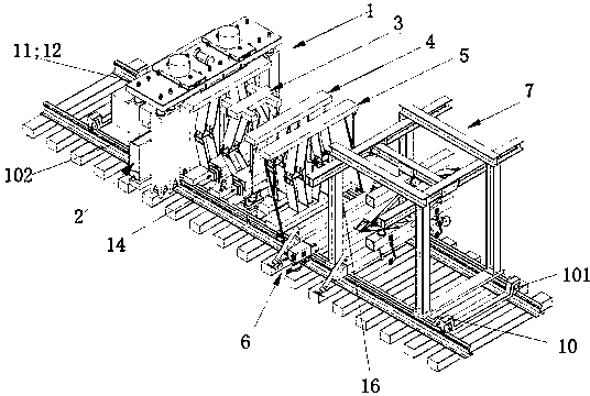
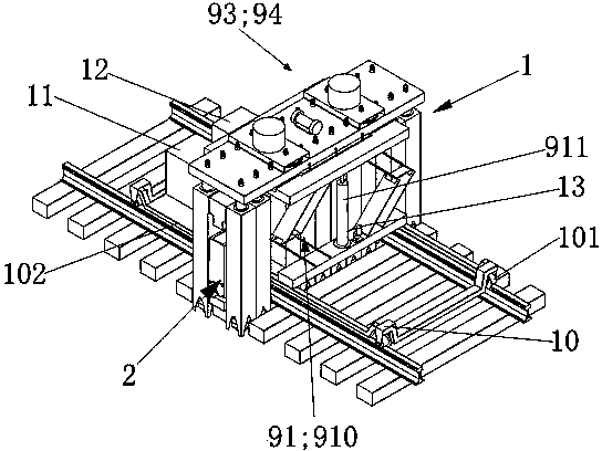
[0154] see figure 1 , Figure 14 , Figure 23 , Figure 30 , Figure 35 , Figure 44 with Figure 57As shown, it is an embodiment of the present invention, which consists of a vibratory rotary excavation stone discharge device 1, a ballast collection and discharge device 2, a vibrating stone pushing device 3, a four-nut synchronous assembly and disassembly device 4, a rail lifting and sleeper device 5, Sleeper push-pull device 6, sleeper lifting device 7, rail car 10, generator 11, hydraulic system box 12, first camera assembly 13, second camera assembly 14, third camera assembly 15, fourth camera assembly 16, fifth A camera assembly 17, a sixth camera assembly 18 and a monitor are formed. The rail car is equipped with a plurality of casters 101 and two longitudinal beams 102, a vibratory rotary excavation and stone discharge device 1, a ballast collection and discharge device 2, a vibrating stone pushing device 3, a four-nut synchronous assembly and disassembly device 4...
PUM
Abstract
The invention discloses a full-mechanical rapid sleeper replacement machine which comprises a vibration rotary excavating and ballast removing device, a ballast collecting and discharging device, a vibration ballast pushing device, a four-nut synchronous assembly and disassembly device, a sleeper lifting and rotating device, a sleeper pushing and pulling device, a sleeper hoisting device, a rail car, a power generator, a hydraulic system box, a first camera assembly, a second camera assembly, a third camera assembly, a fourth camera assembly, a fifth camera assembly, a sixth camera assembly and a monitor. A plurality of casters and two longitudinal beams are arranged on the rail car, the vibration rotary excavating and ballast removing device, the ballast collecting and discharging device, the vibration ballast pushing device, the four-nut synchronous assembly and disassembly device, the sleeper lifting and rotating device, the sleeper pushing and pulling device, the sleeper hoisting device, the power generator and the hydraulic system box are arranged on the two longitudinal beams of the rail car, and the monitor is arranged in a cab of a tow tractor. The full-mechanical rapid sleeper replacement machine is suitable for rapid sleeper replacement on straight-line and curved rail rod segments, operating time in repairing skylight through limited line can be made full and reasonable use of, and full-mechanical sleeper replacement can be achieved.
Description
technical field [0001] The invention relates to a railway maintenance machine, in particular to a fully mechanized fast pillow changing machine. Background technique [0002] During the long-term use of railway sleepers, due to natural settlement and vibration, some railway sleepers sink and need maintenance. Individual sleepers are damaged and need to be replaced in time. In the process of sleeper replacement, manual work is time-consuming and laborious. The efficiency is low, and the work cannot be completed in the effective train passage gap (commonly known as: skylight). Contents of the invention [0003] The purpose of the present invention is to provide a fully mechanized fast pillow changing machine. [0004] The present invention consists of a vibrating rotary excavation device, a ballast collecting and discharging device, a vibrating stone pushing device, a four-nut synchronous assembly and disassembly device, a rail lifting and sleeper device, a push-pull sleepe...
Claims
Application Information
Patent Timeline
Application Date:The date an application was filed.
Publication Date:The date a patent or application was officially published.
First Publication Date:The earliest publication date of a patent with the same application number.
Issue Date:Publication date of the patent grant document.
PCT Entry Date:The Entry date of PCT National Phase.
Estimated Expiry Date:The statutory expiry date of a patent right according to the Patent Law, and it is the longest term of protection that the patent right can achieve without the termination of the patent right due to other reasons(Term extension factor has been taken into account ).
Invalid Date:Actual expiry date is based on effective date or publication date of legal transaction data of invalid patent.