Rail transit platform screen door lock and rail transit platform screen door

A technology for rail transit and screen doors, which is applied to building locks, non-mechanical transmission-operated locks, buildings, etc., can solve the problems of complex structure of screen door locking and unlocking devices, unsmooth locking and unlocking process, and low control accuracy, achieving Reduce processing costs and installation requirements, smooth unlocking process, and simple overall structure

Active Publication Date: 2014-12-10
HANGZHOU OPTIMAX TECH
View PDF5 Cites 16 Cited by
  • Summary
  • Abstract
  • Description
  • Claims
  • Application Information

AI Technical Summary

Problems solved by technology

However, the locking and unlocking device for the shielded door has a complex structure, and the locking and unlocking process is

Method used


Image

  • Rail transit platform screen door lock and rail transit platform screen door
  • Rail transit platform screen door lock and rail transit platform screen door
  • Rail transit platform screen door lock and rail transit platform screen door

Examples


Example Embodiment

[0043] Example 1

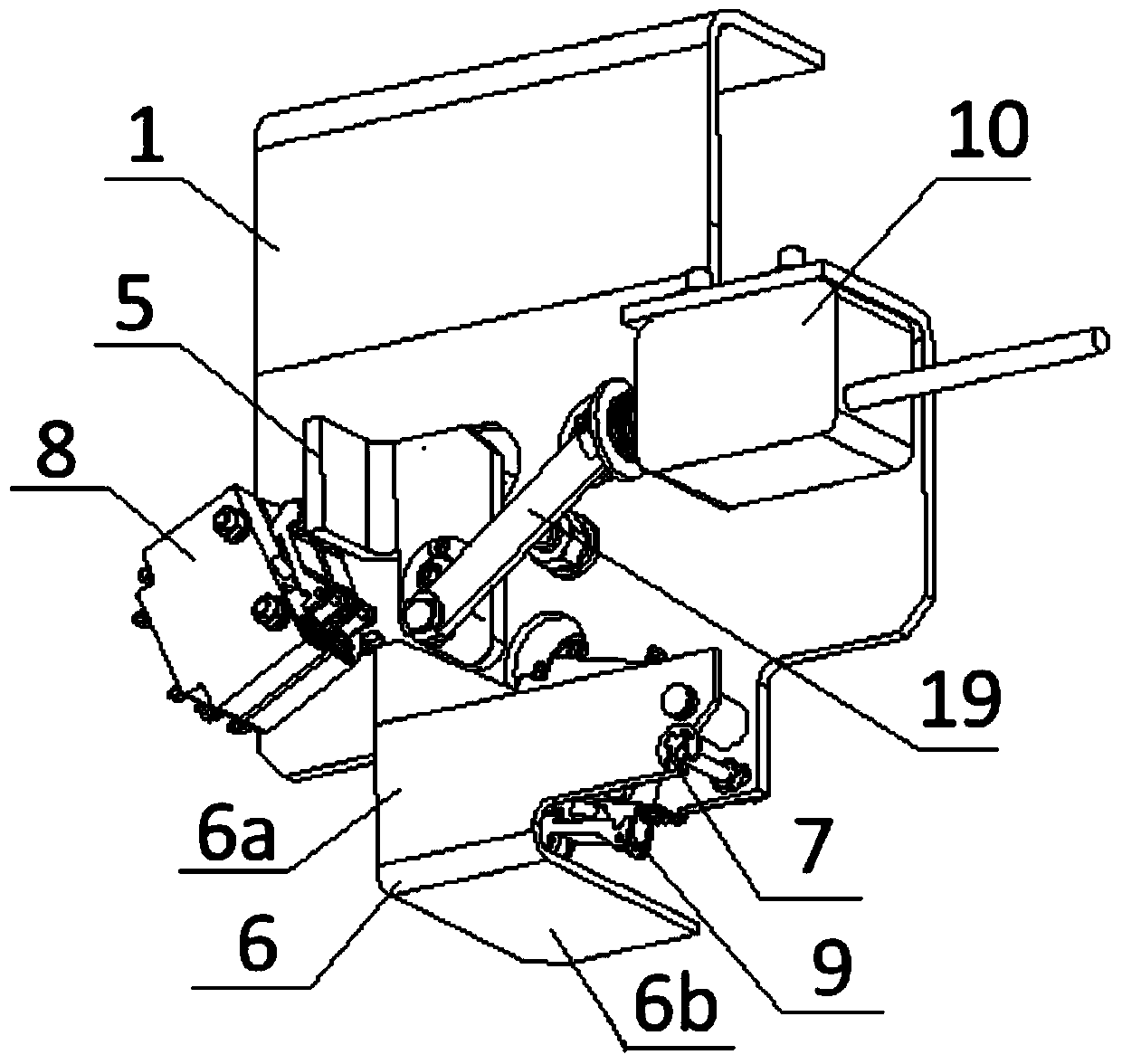
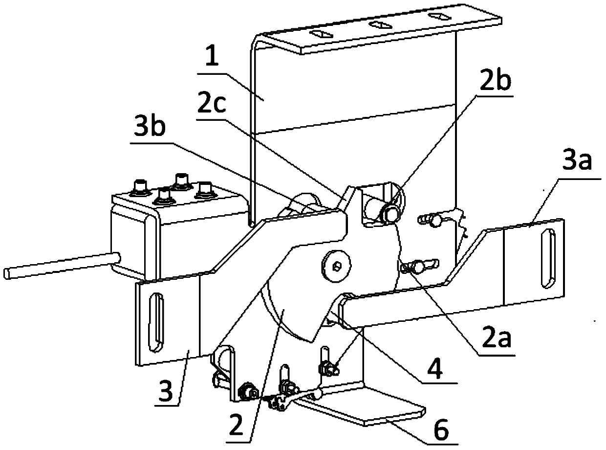
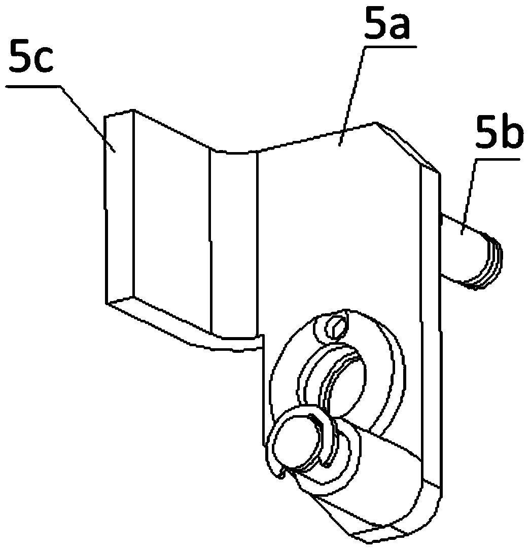
[0044] Such as Figure 1 to Figure 6 As shown, a rail transit screen door lock includes a mounting base 1, and a locking mechanism provided on the mounting base 1. The locking mechanism includes: a lock disk 2 pivotally connected to the mounting base 1 for locking the sliding door, The lock disc 2 is provided with a lock opening 4 that cooperates with the sliding door lock pin 3; the lock disc 2 has a locking position that limits the sliding door lock pin 3 in the lock opening 4, and a release position that releases the sliding door lock pin 3 ; The lock arm 5 transferred to the mounting seat 1, the lock arm 5 has a first working position against the lock disk 2 to keep the lock disk 2 in the locked or released position, and the second release lock disk 2 Working position; a driving mechanism that drives the lock arm 5 to switch between the first working position and the second working position; the manual unlocking plate 6 that drives the lock arm 5 to switch...

Example Embodiment

[0054] Example 2

[0055] Such as Figure 1 to Figure 6 As shown, a rail transit screen door includes a sliding door with a lock pin (not shown in the figure) and a door lock that locks the sliding door lock pin 3, and the structure of the door lock is shown in Embodiment 1. In this embodiment, there are two symmetrical sliding doors. Such as Figure 5 As shown, the lock pin 3 includes a mounting arm 3a fixed to the corresponding sliding door, and a lock column 3b that is transferred to the end of the mounting arm 3a, and the lock column 3b is matched with the lock opening 4.

[0056] The operation process of the rail transit screen door in this embodiment is as follows:

[0057] During the door closing process, the electromagnetic push rod 10 does not work at this time, the first travel switch 8 is in the door opening monitoring state and the lock arm 5 is only affected by the elastic force of the return spring of the electromagnetic push rod 10, and the positioning pin is always ...


PUM


Abstract

The invention discloses a rail transit platform screen door lock. The lock comprises a mounting base and a locking mechanism arranged on the mounting base. The locking mechanism comprises a lock disc arranged on the mounting base through a rotating shaft, a lock arm arranged on the mounting arm and a drive mechanism. A lock opening matched with a sliding door lock pin is arranged on the lock disc. The lock disc is provided with a lock-up position for limiting the sliding door lock pin in the lock opening and a releasing position for releasing the sliding door lock pin. The lock arm is provided with a first working position abutting against the lock disc to keep the lock disc in the lock-up position state or in the releasing position state and a second working position for releasing the lock disc. The drive mechanism is used for driving the lock arm to be switched between the first working position and the second working position. The invention further discloses a rail transit platform screen door. By means of the rail transit platform screen door lock and the rail transit platform screen door, the lock disc and the lock arm are controlled in a linkage mode, the drive mechanism is combined to drive the lock arm to move so as to achieve the function of closing or locking of the sliding door lock, the overall structure is simple, the processes of locking and unlocking are smooth, and accuracy is high.

Description

technical field [0001] The invention belongs to the technical field of rail transit shield door design, and in particular relates to a rail transit shield door lock and a rail transit shield door. Background technique [0002] In the screen door industry, the sliding door is an important channel between the daily operating track and the platform, and it is also an important unit to ensure the safety of passengers. The door lock is an important mechanism in security. [0003] The design of the door lock must include two important functional contents: 1. When the sliding door is driven by the motor through the belt to the closed state, the lock pin of the sliding door activates the door lock to lock. , the sliding door cannot be opened by external force, thus playing a role of safety locking. And when the door lock receives the unlock signal, the electromagnet (electromagnetic push rod) in the door lock is energized and activated, and is unlocked through the connecting rod. ...

Claims


Application Information

Patent Timeline
IPC IPC(8): E05B65/08E05B47/06E05B15/00E05B17/22
Inventor 林杨滨孙登旭
Owner HANGZHOU OPTIMAX TECH
Why Eureka
Try Eureka