Box type raw silk dryer

A box-type, dryer technology, applied in dryers, progressive dryers, drying and other directions, can solve the problems of long time, high cost, complex structure, etc., and achieve simple structure, low cost and convenience. control effect

Active Publication Date: 2016-03-30
江苏铭鹏装备有限公司
View PDF5 Cites 0 Cited by
  • Summary
  • Abstract
  • Description
  • Claims
  • Application Information

AI Technical Summary

Problems solved by technology

At present, the cost of drying equipment is relatively high, and the structure is complex and takes a long time to maintain.

Method used


Image

  • Box type raw silk dryer
  • Box type raw silk dryer
  • Box type raw silk dryer

Examples


Embodiment 1

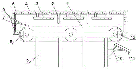
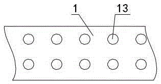
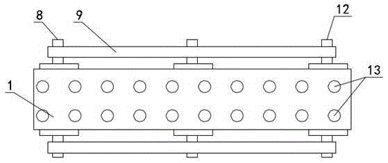
[0022] like figure 1 , figure 2 , image 3 and Figure 4 As shown, the box-type raw silk dryer includes a workbench 9, a driving roller 8, a driven roller 12 and a box body 5, one driving roller 8 is arranged on the left side of the workbench 9, and two driven rollers 12 One, respectively arranged in the middle and the right side of the workbench 9, a driving roller 8 and two driven rollers 12 are evenly distributed laterally on the workbench 9, and a conveyor belt 1 is installed on the driving roller 8 and the driven roller 12 , the box body 5 is above the conveyor belt 1, and the bottom of the box body 5 is fixed on the workbench 9. The conveyor belt 1 is made of heat-resistant material, and the upper left corner of the box body 5 is provided with an inlet for raw silk drying. The feed plate 6 and the feed plate 6 are fixed on the upper left side of the workbench 9 through the feed plate bracket 7. The angle between the feed plate 6 and the conveyor belt 1 is 25 degrees,...

Embodiment 2

[0026] This embodiment is changed on the basis of Embodiment 1, the angle between the feed plate 6 and the conveyor belt 1 is changed to 30 degrees, and the distance between the feed end of the feed plate 6 and the conveyor belt 1 becomes 40mm, the distance between the feeding end of the discharge plate 11 and the conveyor belt 1 becomes 40mm, the distance between the bottom of the separator 2 and the conveyor belt 1 becomes 500mm, the thickness of the insulation layer 4 becomes 30mm, and the adjacent ventilation The spacing between the holes 13 becomes 500 mm. Others are the same as embodiment one.

Embodiment 3

[0028] This embodiment is changed on the basis of Embodiment 1, the angle between the feed plate 6 and the conveyor belt 1 is changed to 28 degrees, and the distance between the feed end of the feed plate 6 and the conveyor belt 1 becomes 30mm, the distance between the feeding end of the discharge plate 11 and the conveyor belt 1 becomes 30mm, the distance between the bottom of the separator 2 and the conveyor belt 1 becomes 300mm, the thickness of the insulation layer 4 becomes 50mm, and the adjacent ventilation The spacing between the holes 13 becomes 400 mm. Others are the same as embodiment one.


PUM


Abstract

The invention relates to a box type original filament dryer, and belongs to the technical field of original filament drying devices. The box type original filament dryer comprises a workbench, a driving roller, a driven roller and a box. The upper left corner of the box is provided with a feeding plate for original filaments to enter the box type original filament dryer, and the lower right corner of the box is provided with a discharging plate for dried original filaments to be output. Three heating mechanisms are arranged above a conveyor belt from left to right in sequence, a partition plate is arranged between every two adjacent heating mechanisms, and the partition plates are fixed into the box. Each heating mechanism comprises a steam pipeline for carrying out heating, an installation frame and an installation casing pipe for the steam pipeline to be installed. According to the box type original filament dryer, the production cost of the dryer is reasonably controlled, the structure is simple, maintaining is convenient, and cost is low. If a water induction device and a temperature induction device are additionally arranged in the box, the drying quality of the original filaments is very convenient to control.

Description

technical field [0001] The invention relates to a box-type raw silk dryer, which belongs to the technical field of raw silk drying equipment. Background technique [0002] Precursor is one of the links in carbon fiber production. Precursor is mainly divided into two parts in the production process, one is polymerization and the other is spinning. The drying of the raw silk spun in the spinning process is also very important, and the control of the moisture content of the raw silk is one of the main factors in the production of carbon fiber. The cost of the equipment currently used for drying is relatively high, and the structure is complex and takes a long time to maintain. Contents of the invention [0003] In view of the above problems, the present invention provides a box-type raw silk dryer, which has a simple structure, convenient maintenance, low cost, convenient control of drying quality, and light weight. [0004] The technical scheme that the present invention t...

Claims


Application Information

Patent Timeline
Patent Type & Authority Patents(China)
IPC IPC(8): F26B15/18F26B23/10
Inventor 陈菊芳
Owner 江苏铭鹏装备有限公司
Why Eureka
Try Eureka