A Piezoelectric Tilting Mirror High-Voltage Driver with Compensation Function of Object Frequency Characteristics

A technology of frequency characteristics and tilting mirrors, applied in instruments, optical components, optics, etc., can solve the problems of mechanical resonance phenomenon of piezoelectric tilting mirrors, drift of analog filter network circuit parameters, and limit engineering practicability, etc., to improve engineering Practicality, providing versatility, and low power consumption

Active Publication Date: 2016-09-28
INST OF OPTICS & ELECTRONICS - CHINESE ACAD OF SCI
View PDF3 Cites 0 Cited by
  • Summary
  • Abstract
  • Description
  • Claims
  • Application Information

AI Technical Summary

Problems solved by technology

For example, in the article "Methods of Improving the Application Bandwidth of High-speed Piezoelectric Tilting Mirrors" in "Optoelectronic Engineering" 2009, Vol. 36, No. 7, page 60, Zhu Heng et al. consider the use of lightweight mirror materials such as SIC from mechanical kinematics to reduce rotation. Inertia, or increase the structural rigidity of the driver and optimize the structural parameters to improve the mechanical resonance frequency of the piezoelectric tilting mirror itself, but its production is very difficult, and the mechanical resonance phenomenon of the fabricated piezoelectric tilting mirror still exists
However, Li Xinyang and others used analog network filter circuits to suppress mechanical resonance in the article "Stable Control of High-Speed ​​Tilting Mirrors in Adaptive Optical Systems" in "Strong Lasers and Particle Beams", Volume 1, Issue 1, 1999, Page 31 , but the engineering practicability of its analog filter network circuit is limited by factors such as parameter drift and difficulty in circuit adjustment

Method used


Image

  • A Piezoelectric Tilting Mirror High-Voltage Driver with Compensation Function of Object Frequency Characteristics
  • A Piezoelectric Tilting Mirror High-Voltage Driver with Compensation Function of Object Frequency Characteristics
  • A Piezoelectric Tilting Mirror High-Voltage Driver with Compensation Function of Object Frequency Characteristics

Examples


Embodiment Construction

[0018] The present invention will be further described below in conjunction with the accompanying drawings and specific embodiments.

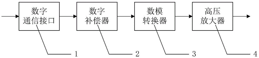
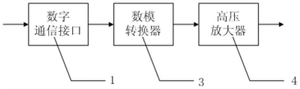
[0019] Such as figure 1 As shown, the piezoelectric tilting mirror high-voltage driver with the compensation function of the target frequency characteristic of the present invention includes a communication interface 1 , a digital compensator 2 , a digital-to-analog converter 3 and a high-voltage amplifier 4 .

[0020] In this embodiment, the communication interface 1 receives the 16-bit digital control voltage signal sent by the wavefront processor through the CAMERALINK interface, and after digital compensation is performed by the digital compensator 2, it is output to the digital-to-analog converter 3 for 16-bit digital-to-analog conversion The device 3 converts the digital signal into an analog signal of -5V~+5V and outputs it to the high-voltage amplifier 4. After being amplified 100 times by the high-voltage amplifier 4, it outputs a hig...


PUM


Abstract

The invention discloses a piezoelectric tilting mirror high-voltage driver with the function of compensating the frequency characteristic of an object, comprising a communication interface (1), a digital compensator (2), a digital-to-analog converter (3), and a high-voltage amplifier (4). It is: the communication interface (1) receives the digital control signal sent by the wave front processor, after performing digital compensation in the digital compensator (2), it enters the digital-to-analog converter (3) and converts it into an analog control signal, and then passes through the high-voltage amplifier (4) Amplify the high-voltage power signal to drive the piezoelectric tilting mirror. The digital compensator can real-time compensate the amplitude response at the mechanical resonance frequency of the piezoelectric tilting mirror, which is the driving object of the high-voltage driver, so as to solve the influence of the mechanical resonance peak of the piezoelectric tilting mirror on the adaptive optical servo system. The invention is suitable for high-speed and high-voltage driving of piezoelectric tilting mirrors in the field of adaptive optical systems.

Description

technical field [0001] The invention relates to the field of adaptive optical systems, in particular to a high-voltage driver of a piezoelectric tilting mirror with the function of compensating the frequency characteristic of an object. Background technique [0002] The piezoelectric tilting mirror is one of the core devices of the adaptive optics system. Its main function is to use a piezoelectric driver with a resolution of nanometers and a response speed of milliseconds to drive a reflector. The driving voltage output by the high-voltage driver makes the beam Controlled high-speed two-dimensional deflection to correct the tilt of the optical system. The composition of the traditional piezoelectric tilting mirror high-voltage driver is as follows: figure 2 As shown, it includes a communication interface 1 , a digital-to-analog converter 3 and a high-voltage amplifier 4 . The communication interface 1 receives the digital control signal sent by the wave front processor, c...

Claims


Application Information

Patent Timeline
Patent Type & Authority Patents(China)
IPC IPC(8): G02B26/08
Inventor 凡木文黄林海李梅饶长辉王晓云
Owner INST OF OPTICS & ELECTRONICS - CHINESE ACAD OF SCI
Why Eureka
Try Eureka