
Real-time compensation decoupling method and compensation decoupling system for spacecraft platform disturbance by spaceborne radar

A spaceborne radar and real-time compensation technology, applied in the direction of antenna support/installation device, etc., can solve the problems of radar antenna missing scan and inability to effectively capture targets, achieve high reliability, eliminate single-point failure modes, and improve reliability and maintenance effects

Active Publication Date: 2017-04-05
SHANGHAI RADIO EQUIP RES INST
View PDF5 Cites 0 Cited by
  • Summary
  • Abstract
  • Description
  • Claims
  • Application Information

AI Technical Summary

Problems solved by technology

In the process of microwave radar searching and scanning targets, if the spacecraft platform itself shakes or autonomously maneuvers, due to the dynamic coupling between the platform and the radar, this coupling factor may cause the radar antenna to miss a certain area and cannot effectively capture Therefore, the spaceborne radar must have a strong ability to suppress platform disturbances and accurately track moving targets

Method used


Image

  • Real-time compensation decoupling method and compensation decoupling system for spacecraft platform disturbance by spaceborne radar
  • Real-time compensation decoupling method and compensation decoupling system for spacecraft platform disturbance by spaceborne radar
  • Real-time compensation decoupling method and compensation decoupling system for spacecraft platform disturbance by spaceborne radar

Examples


Embodiment Construction

[0043] Specific embodiments of the present invention will be further described below in conjunction with the accompanying drawings.

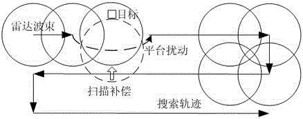
[0044] Such as figure 1 As shown, during the search process of the spaceborne microwave radar, the radar antenna scans in a zigzag shape along the azimuth dimension or the high and low dimensions under the control of its two-dimensional drive mechanism. Search, capture, track and measure. Such as figure 1 As shown in the dotted box in the middle, the coupling of the spacecraft platform disturbance to the two-dimensional drive mechanism causes a certain offset of the radar beam perpendicular to the scanning direction. If the target is just outside the dotted box at this time, the microwave radar will not be able to capture the target, resulting in microwave Radar capture probability reduced.

[0045] The invention discloses a method for real-time compensation and decoupling of spaceborne radar for space vehicle platform disturbance and its a...


PUM


Abstract

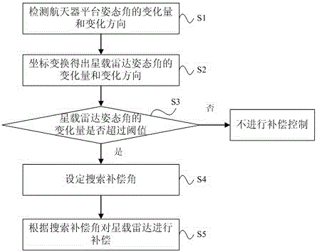
The invention discloses a real-time compensation decoupling method for spacecraft platform disturbance by a spaceborne radar. The method includes that when the spaceborne radar searches, a three-axis stabilization rate gyroscope real-timely detects changing amount and changing direction of a spacecraft platform attitude angle; the changing amount and the changing direction of the spacecraft platform attitude angle are subjected to transformation of coordinates to obtain changing amount and changing direction of a spaceborne radar attitude angle; when the changing amount of the spaceborne radar attitude angle exceeds a preset threshold value, the spaceborne radar sets a searching compensatory angle; the value of the searching compensatory angle is the changing amount of the spaceborne radar attitude angle; the compensation direction of the searching compensatory angle is vertical to the searching direction of the spaceborne radar and opposite to the changing direction of the spaceborne radar attitude angle; a servo mechanism of the spaceborne radar performs real-time compensation controlling on the spaceborne radar attitude angle according to the searching compensatory angle. According to the real-time compensation decoupling method and a compensation decoupling system for spacecraft platform disturbance by the spaceborne radar, own resources of a spacecraft platform are utilized, real-time compensation of the servo mechanism of the spaceborne radar is achieved, valuable volume, weight, and power consumption resources of a spacecraft can not be occupied, and resources are saved.

Description

technical field [0001] The invention relates to a space vehicle platform disturbance real-time compensation decoupling technology in the aerospace field, in particular to a real-time compensation decoupling method and a compensation decoupling system for space vehicle platform disturbance when a spaceborne radar is in orbit. Background technique [0002] Space-borne microwave radar is an important target acquisition, tracking and relative measurement task load of the spacecraft platform. Generally, the servo mechanism is used to drive the radar antenna to conduct azimuth, high and low two-dimensional search of the designated airspace. In the process of microwave radar searching and scanning targets, if the spacecraft platform itself shakes or autonomously maneuvers, due to the dynamic coupling between the platform and the radar, this coupling factor may cause the radar antenna to miss a certain area and cannot effectively capture Therefore, it is required that the spaceborne...

Claims


Application Information

Patent Timeline
Patent Type & Authority Patents(China)
IPC IPC(8): H01Q1/18
Inventor 李雁斌吉峰黄勇蔡昆邹波江利中
Owner SHANGHAI RADIO EQUIP RES INST
Learn More