High-precision surface type measuring system

A measurement system and high-precision technology, applied in the direction of measuring devices, instruments, optical devices, etc., can solve problems such as difficult to achieve nano-scale surface accuracy measurement, achieve good tracking effect, reduce errors, and stabilize the rotation of the workpiece

Pending Publication Date: 2021-05-28
四川欧瑞特光电科技有限公司
View PDF0 Cites 1 Cited by
  • Summary
  • Abstract
  • Description
  • Claims
  • Application Information

AI Technical Summary

Problems solved by technology

[0011] In order to solve the problem that the surface measurement system in the prior art is difficult to measure the surface precision of spherical, aspheric and free-form surfaces, etc., a high-precision surface measurement system is provided.

Method used


Image

  • High-precision surface type measuring system
  • High-precision surface type measuring system
  • High-precision surface type measuring system

Examples


Embodiment 1

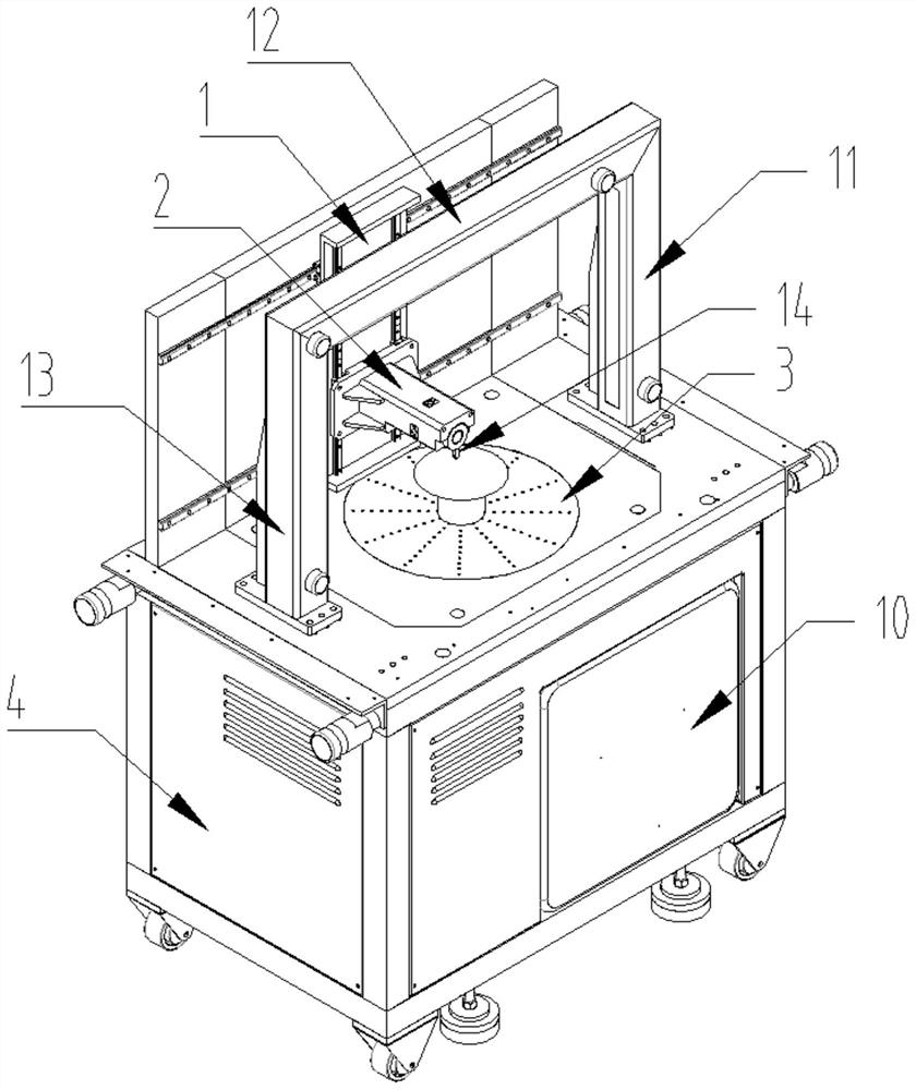
[0035] A high-precision surface measurement system, such as figure 1 As shown, it includes the real-time feedback system, motion scanning system 1, real-time positioning laser system 2, rotary table 3 and support frame 4, and the rotary table 3, real-time feedback system and motion scanning system 1 are all installed on the support frame 4. The positioning laser system 2 is installed on the motion scanning system 1. The real-time positioning laser system 2 includes a rotation axis 7 on which a spectral confocal measuring head 14 is installed. The motion scanning system 1 includes an X-direction motion pair 5, and an X-direction motion pair 5 is equipped with a Z-direction motion pair 6, and the rotating shaft 7 is installed on the Z-direction motion pair 6 through a mounting bracket, and a laser displacement sensor is installed on the mounting bracket.

[0036] Such as Figure 5 As shown, in order to realize the normal tracking of the spectral confocal probe 14 along the surf...

Embodiment 2

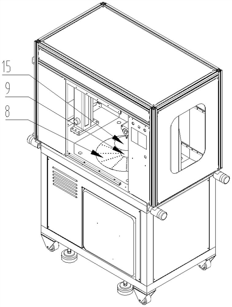
[0039] On the basis of Example 1, such as figure 2 As shown, the rotary table 3 includes a rotary mechanism 8 installed on the support frame 4, and the workpiece fixing seat 9 is installed on the rotary mechanism 8. Both the rotary mechanism 8 and the motion scanning system 1 are connected with a motion host 10, and the motion host 10 is installed on the Support frame 4 inside.

[0040] Preferably, an air flotation system is provided under the slewing mechanism 8 . The air flotation system can establish a fixed range of air conditions around the workpiece 15 to be measured, which reduces the influence of temperature, humidity, and wind speed on the measurement structure during the measurement process of the entire system, and prevents large errors due to differences in air conditions.

Embodiment 3

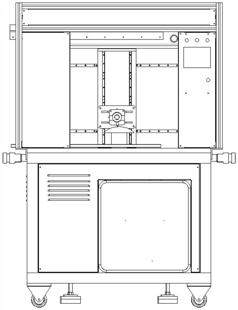
[0042] On the basis of Example 1, such as Figure 3-4As shown, the real-time feedback system includes a positioning reference frame 11 and a plurality of plane mirrors. The positioning reference frame 11 is installed above the rotary table 3, and the plane mirrors are all installed on the positioning reference frame 11. 12 and Z direction reflector 13 to form.


PUM


Abstract

The invention discloses a high-precision surface type measuring system, belongs to the technical field of high-precision surface type measuring instruments, and solves the problem that a surface type measuring system in the prior art is difficult to realize nanoscale surface type precision measurement on irregular curved surfaces such as spherical surfaces, aspheric surfaces and free-form surfaces. The system comprises a real-time feedback system, a motion scanning system, a real-time positioning laser system, a rotating table and a supporting frame, the rotating table, the real-time feedback system and the motion scanning system are all installed on the supporting frame, the real-time positioning laser system is installed on the motion scanning system, and the real-time positioning laser system comprises a rotating shaft. A spectrum confocal measuring head is installed on the rotating shaft, the motion scanning system comprises an X-direction kinematic pair, a Z-direction kinematic pair is installed on the X-direction kinematic pair, the rotating shaft is installed on the Z-direction kinematic pair through an installation support, and a laser displacement sensor is installed on the installation support. The system is used for high-precision surface type measurement of the workpiece, the measurement error is small, and the influence of the environment is small.

Description

technical field [0001] The invention belongs to the technical field of high-precision surface shape measuring instruments, and in particular relates to a high-precision surface shape measuring system. Background technique [0002] High-precision surface measuring instrument is an electronic measuring instrument used in the fields of information science, system science and mechanics. [0003] In production and scientific research practice, it is often necessary to measure the surface profile of many objects, that is, to measure the microstructure of the surface. In many cases, it is rare and important to know the three-dimensional structure of the surface, especially the fine three-dimensional structure. The most common surface shape measurement method in the prior art is to photograph the surface of an object, and obtain an image of the object to be measured from a direction perpendicular to the surface to be measured. But it is obvious that no matter how high the accuracy...

Claims


Application Information

Patent Timeline
Patent Type & Authority Applications(China)
IPC IPC(8): G01B11/24
CPCG01B11/24
Inventor 王玉鲁范朦蒋毅杨龙范松如罗荣荣
Owner 四川欧瑞特光电科技有限公司
Why Eureka
Try Eureka