Band steel traction connection structure and band penetration method for continuous band steel unit

A technology for connecting structures and traction belts, which is applied in the direction of bending workpieces, metal processing equipment, metal rolling, etc., can solve the problems of excessive tension of traction belts, broken belts, and low production efficiency, and prevent uneven distribution and ring formation The structure is firm and avoids the effect of excessive concentration

Inactive Publication Date: 2014-12-17
PANGANG GRP PANZHIHUA STEEL & VANADIUM
View PDF9 Cites 3 Cited by
  • Summary
  • Abstract
  • Description
  • Claims
  • Application Information

AI Technical Summary

Problems solved by technology

Due to the long production line of the entire strip steel continuous unit, multiple operators are required to be distributed in different positions of the production line for strip threading operations. During the strip threading operation, multiple operators need to work together to make each section of the traction belt on the production line It runs synchronously forward, so the cooperative operation ability of each operator is very high. If the coordination of each operator is not good, it will cause excessive tension in some parts of the traction belt and break the belt. Due to the large number of personnel, the coordination process is cumbersom

Method used


Image

  • Band steel traction connection structure and band penetration method for continuous band steel unit
  • Band steel traction connection structure and band penetration method for continuous band steel unit
  • Band steel traction connection structure and band penetration method for continuous band steel unit

Examples


Embodiment Construction

[0028] The present invention will be further described below in conjunction with accompanying drawing.

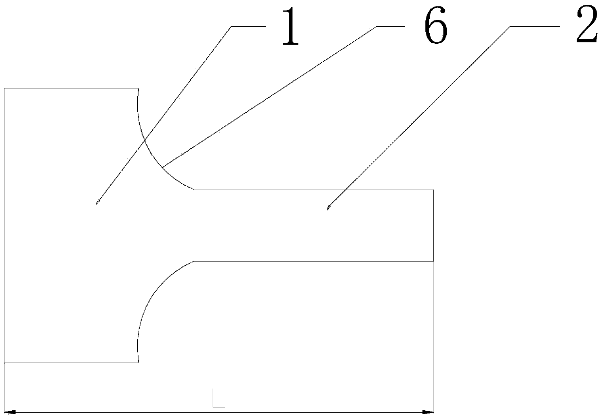
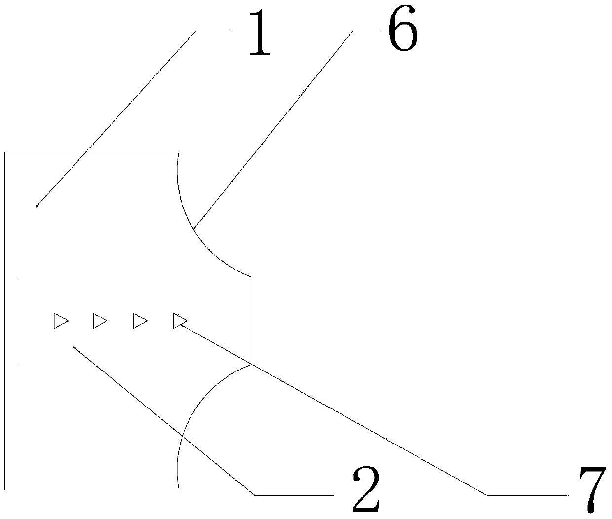
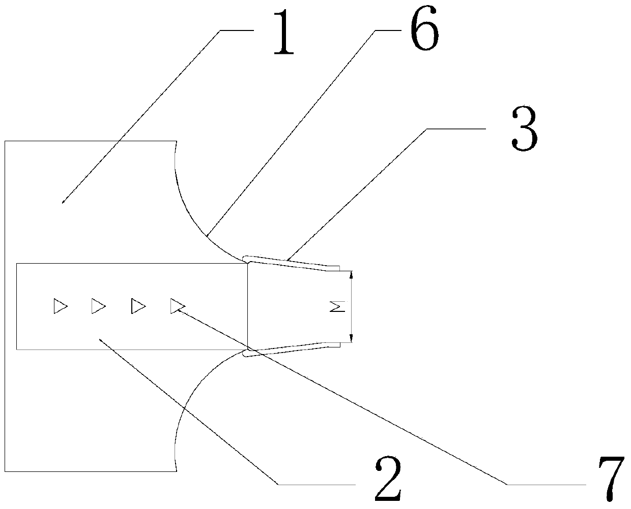
[0029] Such as figure 1 , figure 2 , image 3 ,and Figure 4 As shown, the strip steel traction connection structure adopted in the present invention comprises a strip steel end 1, a strip steel traction head 2, a pull ring 3 and a traction belt 4, and the two ends of the strip steel traction head 2 are connected to the strip steel end 1 connected to form a ring structure, one end of the pull ring 3 passes through the ring structure, and the other end is connected to the traction belt 4, one end of the strip steel traction head 2 is an integrated structure with the strip steel end 1, The other end is riveted on the strip end 1 . One end of the strip puller 2 is an integrated structure with the strip end 1, and the other end is riveted on the strip end 1, which can make the ring structure more reliable and is not easy to be connected by the pull ring 3 during the strip ...


PUM

PropertyMeasurementUnit
Widthaaaaaaaaaa
Diameteraaaaaaaaaa
Openingaaaaaaaaaa

Abstract

The invention discloses a band steel traction connection structure and a band penetration method for a continuous band steel unit, and particularly relates to the field of band steel production. The band steel traction connection structure which is firm in connection, is capable of reducing the band breaking frequency and is provided by the invention comprises a band steel end part, a band steel traction head, a pull ring and a traction band, wherein one end of the band steel traction head and the band steel end part are of an integrated structure, and the other end of the band steel traction head is riveted on the band steel end part, so that an annular structure is firmer. The band penetration method for the continuous band steel unit, which is provided by the invention, comprises the following steps: a, lowering a loop trolley to a zero position; b, winding the traction band around each roller group; c, fixedly connecting the band steel traction connection structure with one end of band steel; d, tensioning a loop; e, filling the loop with the traction band; f, performing band penetration operation. The tension of the traction band is accurately controlled through automatic tension control equipment, so that breaking of the traction band due to the fact that a certain part is over-tensioned is avoided.

Description

technical field [0001] The invention relates to a strip steel traction connection structure and a strip steel continuous unit threading method, in particular to a strip steel traction connection structure and a strip steel continuous unit threading method in the field of strip steel production. Background technique [0002] In the process of strip steel production, the strip steel needs to be composed of strip steel production equipment such as uncoiler, entry nip roller, tension roller group, entry turning roller, looper trolley, stabilizing roller, exit nip roller, oiler, coiler, etc. Driven by the roller group of the unit, the medium continuously moves through each production equipment at one time, so as to realize the continuous production of strip steel. The strip steel needs to be tightened during the continuous movement, that is, the strip steel must have a certain tension. Before the normal operation of the strip steel, it is necessary to use the traction belt conne...

Claims


Application Information

Patent Timeline
IPC IPC(8): B21B41/00
Inventor 汤波高超于正敏
Owner PANGANG GRP PANZHIHUA STEEL & VANADIUM
Why Eureka
Try Eureka