Pin bending equipment
A bending and equipment technology, applied in electrical components, inductance/transformer/magnet manufacturing, circuits, etc., can solve the problems of connection failure between pins and network transformer bases, inconvenient bending accuracy with small deformation, and achieve accurate spacing deformation. , the structure is simple, the effect of protecting the connection relationship
- Summary
- Abstract
- Description
- Claims
- Application Information
AI Technical Summary
Problems solved by technology
Method used
Image

Examples
Embodiment 1
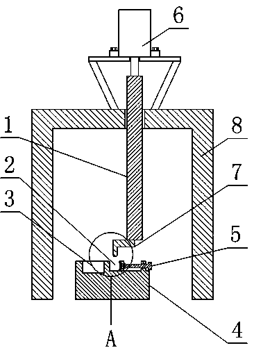
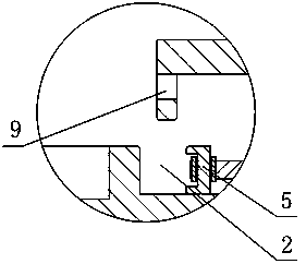
[0022] Such as Figure 1 to Figure 3 As shown, a pin bending equipment includes a frame 8, a vertical pressing bar 1 arranged on the frame 8, a deformed pressing block 7 fixed on the lower end of the pressing bar 1, and a The material table 4, the pressure rod 1 can move along its axial direction, the material table 4 is also provided with a groove width adjustment part 5, and a facing deformation briquetting block is formed between the groove width adjustment part 5 and the material table 4 7 and a bending groove 2 with adjustable width; the deformed pressing block 7 is also provided with an accommodating hole 9 .
[0023] In this embodiment, the deformed briquetting block 7 is set to have an L-shaped cross-section, any side of the deformed briquetting block 7 is located in the vertical direction, and the accommodating hole 9 is located on the side where the deformed briquetting block 7 is located in the vertical direction. During the bending process, under the compressive s...
Embodiment 2
[0025] The present embodiment is further limited on the basis of embodiment 1, as Figure 1 to Figure 3 As shown, in order to drive the pressing rod 1 conveniently, the upper end of the pressing rod 1 is also fixedly connected with a pressing rod driving part. According to the size of the workload, the set pressure rod driving part can be set in the structural form of artificial compressive stress drive or hydraulic pressure or air pressure drive.
[0026] In order to facilitate the working efficiency of the present invention, to facilitate the switching of working states and to simplify the structure of the driving part of the pressing rod, the driving part of the pressing rod is an air cylinder 6 .
Embodiment 3
[0028] The present embodiment is further limited on the basis of embodiment 1, as Figure 1 to Figure 3 As shown, in order to make the pin and the material table 4 only produce the active force positioned at the axial direction of the pressure rod 1, which is beneficial to the working quality of the present invention, the upper surface of the material table 4 is stepped, and the material table 4 is also An accommodating slot 3 for placing the base and cover of the network transformer is provided.
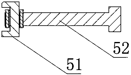
[0029] In order to simplify the structure of the groove width adjustment part 5, the groove width adjustment part 5 includes a screw rod 52 threadedly connected with the material table 4 and a supporting table 51 with a clearance fit with the screw rod 52, and the position of the supporting table 51 is fixed on the axis of the screw rod 52 . In the above structure, the purpose of changing the width of the bending groove 2 is achieved by rotating the screw 52 to brake the movement o...
PUM
 Abstract
Description
Claims
Application Information
 - R&D
- Intellectual Property
- Life Sciences
- Materials
- Tech Scout
- Unparalleled Data Quality
- Higher Quality Content
- 60% Fewer Hallucinations
Browse by: Latest US Patents, China's latest patents, Technical Efficacy Thesaurus, Application Domain, Technology Topic, Popular Technical Reports.
© 2025 PatSnap. All rights reserved.Legal|Privacy policy|Modern Slavery Act Transparency Statement|Sitemap|About US| Contact US: help@patsnap.com