Hollow ingot casting mold and method for casting hollow ingot by using same

A hollow steel and mold technology is applied in the field of hollow steel ingot casting molds and the field of casting hollow steel ingots using the same. Volume, easy demoulding, and the effect of reducing tension

Inactive Publication Date: 2014-12-17
HUBEI CHANGYU MOLD MATERIAL
View PDF5 Cites 4 Cited by
  • Summary
  • Abstract
  • Description
  • Claims
  • Application Information

AI Technical Summary

Problems solved by technology

[0003] After the hollow steel ingot is poured, the steel ingot is closely attached to the mold, which makes demoulding difficult
In order to overcome the above problems, the mold is generally designed to have different sizes at the upper and lower ends. In this way, the demoulding of the steel ingot is relatively easy, but the shape and size of the hollow steel ingot cast from this will also be affected by the shape of the mold, and the upper and lower ends have different sizes. and other shapes, resulting in a reduction in the usable volume of the hollow ingot

Method used


Image

  • Hollow ingot casting mold and method for casting hollow ingot by using same
  • Hollow ingot casting mold and method for casting hollow ingot by using same
  • Hollow ingot casting mold and method for casting hollow ingot by using same

Examples


no. 1 example

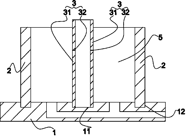
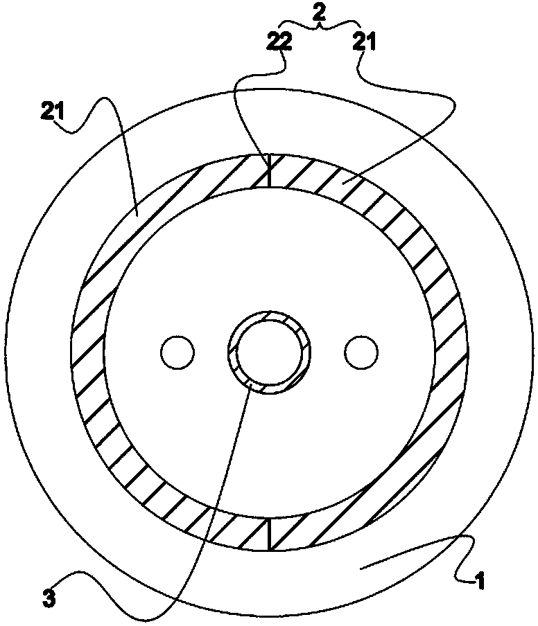
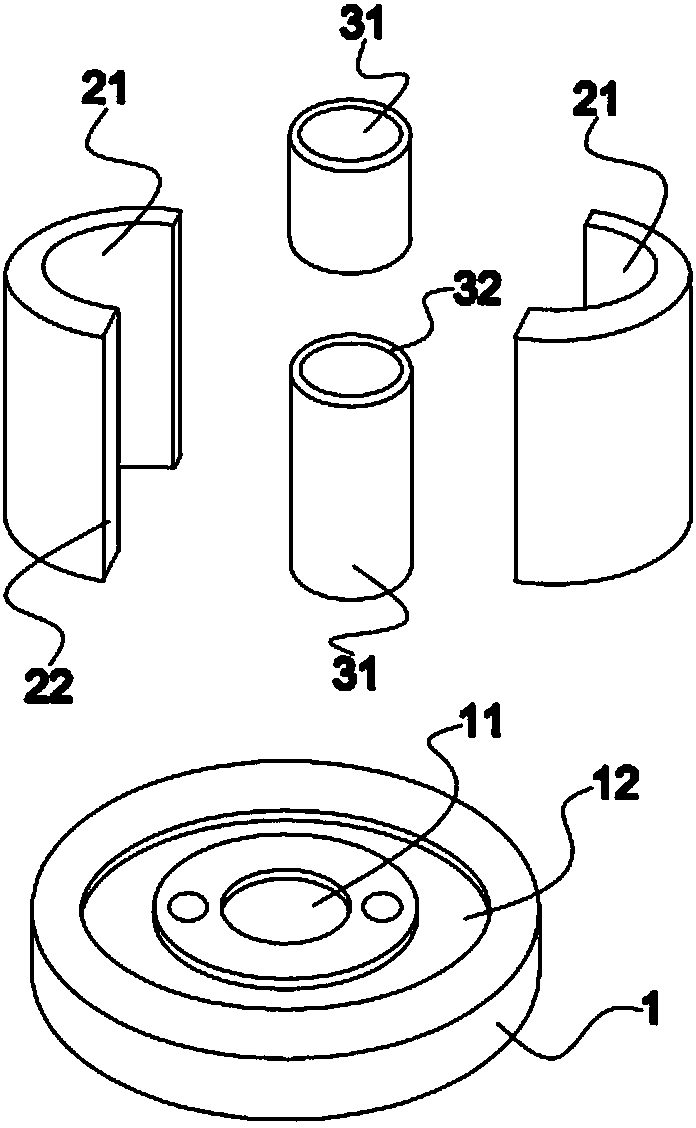
[0025] First, assemble the hollow steel ingot pouring mold. First set each short mandrel 31 in the first groove 11 of the base 1 from top to bottom and seal it well; then assemble each half outer mold 21 in the second groove 12 of the base 1 and seal it well .

[0026] Next pouring, pouring molten steel until the molten steel is evenly filled in the cavity 5 between the outer mold 2 and the core mold 3, and the liquid steel level is lower than the top of the core mold 3 and the outer mold 2.

[0027] Then cool down and solidify, and cool down the casting mold and molten steel to crystallize the molten steel. The temperature of the core mold 3 and the outer mold 2 can be cooled at the same time, so as to ensure that the solidification line of the molten steel is as close as possible to the center line of the end surface of the steel ingot. The outer mold 2 can cool down by radiating heat to the surrounding air, and the inside of the core mold 3 can be fed with cooling gas or ...

no. 2 example

[0030] The method of pouring hollow steel ingots in the second embodiment of the present invention is basically the same as that in the first embodiment, the difference lies in the process of assembling the casting molds for hollow steel ingots: first, each short mandrel 31 is sleeved on the first part of the base 1 from top to bottom. The first groove 11 is sealed well; then the temperature-resistant layer is evenly arranged on the outer wall of the mandrel 3, and the thickness is set to 3-10mm; finally, each half outer mold 21 is assembled and sleeved in the second groove 12 of the base 1 And seal it well.

no. 3 example

[0032] The method for pouring hollow steel ingots in the third embodiment of the present invention is basically the same as that in the first embodiment, the difference lies in the process of assembling the casting molds for hollow steel ingots: first, each short mandrel 31 is set on the first part of the base 1 from top to bottom. The first groove 11 is sealed well; then the temperature-resistant layer is evenly arranged on the outer wall of the mandrel 3, and the thickness is set to 3-10 mm; then each half outer mold 21 is assembled and set in the second groove 12 of the base 1 And sealed well; finally, the temperature-resistant layer is evenly arranged on the inner wall of the outer mold 2 .

[0033] Compared with the prior art, the beneficial effect of the present invention is that the hollow steel ingot casting mold provided by the present invention divides the outer mold 2 into a plurality of half outer molds 21, and divides the core mold 3 into a plurality of short core ...


PUM

PropertyMeasurementUnit
thicknessaaaaaaaaaa

Abstract

The invention provides a hollow ingot casting mold which comprises a base, a hollow columnar outer mold and a columnar core mold, wherein the outer mold comprises two or more than two half outer molds which are mutually matched and sealed; the core mold comprises two or more than two columnar short core molds which are mutually matched and sealed; the core mold and the outer mold are sealed on the base along a same center shaft and the core shaft is put in the outer mold; the base, the core mold and the outer mold form a cavity. According to the hollow ingot casting mold provided by the invention, the outer mold is divided into multiple half outer molds, and the core mold is divided into multiple half short core molds, so that the tensile force between the mold and an ingot during a demolding process is reduced and demolding is convenient; furthermore, the hollow ingot casting mold and the casting method which are provided by the invention can be used for casting a hollow ingot with the same upper and lower end size, so that the available volume of the hollow ingot is improved.

Description

[0001] technical field [0002] The invention relates to a casting mold for steel ingots and a casting method for steel ingots, in particular to a casting mold for hollow steel ingots and a method for casting hollow steel ingots using the same. Background technique [0003] After the hollow steel ingot is poured, the steel ingot is closely attached to the mold, which makes demoulding difficult. In order to overcome the above problems, the mold is generally designed to have different sizes at the upper and lower ends. In this way, the demoulding of the steel ingot is relatively easy, but the shape and size of the hollow steel ingot cast from this will also be affected by the shape of the mold, and the upper and lower ends have different sizes. and other shapes, resulting in a reduction in the available volume of the hollow steel ingot. [0004] Contents of the invention [0005] In view of this, the object of the present invention is to provide a hollow steel ingot casti...

Claims


Application Information

Patent Timeline
Patent Type & Authority Applications(China)
IPC IPC(8): B22D7/04B22D7/08
Inventor 付益明伍思杨
Owner HUBEI CHANGYU MOLD MATERIAL
Why Eureka
Try Eureka