Integrated disassembling device for lining plate bolt and flange plate of large grinding machine

A technology for dismantling devices and mills, which is applied in metal processing, metal processing equipment, manufacturing tools, etc., can solve the problems of reduced construction safety, high labor intensity, and difficulty in disengaging from the feed port, so as to improve disassembly efficiency and reduce labor costs. The effect of labor intensity

Inactive Publication Date: 2014-12-17
郑州贝龙液压技术有限公司
View PDF8 Cites 3 Cited by
  • Summary
  • Abstract
  • Description
  • Claims
  • Application Information

AI Technical Summary

Problems solved by technology

Bolts are pierced from the inside to the outside, and there are nuts on the outer ends of the bolts. When removing the bolts, first remove the nuts, and then drive the bolts inwards. Manual work is not only labor-intensive, but also prolongs the large-scale operation to a large extent. The time for mill maintenance is reduced, and the safety of construction is also reduced
[0004] Since the feed port of the wet mill is in contact with the material for a long time, it is often difficult to remove the flange of the feed port of the mill from the feed port. It is time-consuming and laborious to remove the flange of the feed port of the mill. If it is purely manual operation , increasing the difficulty of construction

Method used


Image

  • Integrated disassembling device for lining plate bolt and flange plate of large grinding machine
  • Integrated disassembling device for lining plate bolt and flange plate of large grinding machine

Examples


Embodiment Construction

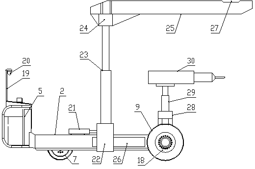
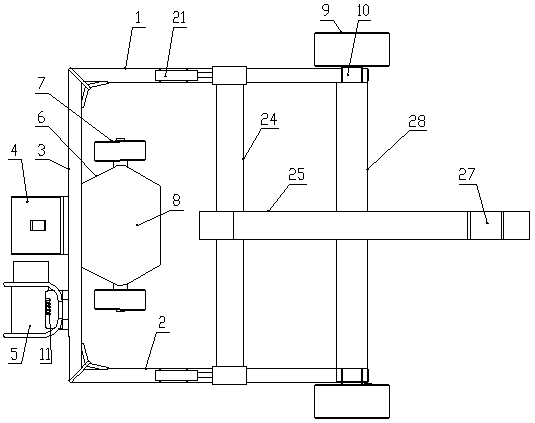
[0027] Such as figure 1 and figure 2 As shown, the large-scale mill liner bolt and flange integrated removal device of the present invention includes a left longitudinal beam 1 and a right longitudinal beam 2 arranged in parallel along the front and rear directions, and the rear end of the left longitudinal beam 1 and the right longitudinal beam 2 The space is connected by a beam 3, the rear side of the beam 3 is provided with a hydraulic power station 4 and the driving console 5, the front side of the beam 3 is provided with a bracket 6, the left and right sides of the bracket 6 are respectively provided with a steering wheel 7, and the bracket 6 is equipped with There is a hydraulic steering system 8 that controls the simultaneous steering of two steering wheels 7, and a driving wheel 9 is provided at the front end of the left longitudinal beam 1 and the right longitudinal beam 2 respectively, and a hydraulic travel motor 10 is connected to the center of each driving wheel ...


PUM


Abstract

The invention discloses an integrated disassembling device for a lining plate bolt and a flange plate of a large grinding machine. The device comprises a left longitudinal beam and a right longitudinal beam which are arranged in parallel along the front-back direction, wherein the rear ends of the left longitudinal beam and the right longitudinal beam are connected through a transverse beam; a hydraulic power station and a driving console are arranged on the rear side of the transverse beam; a bracket is arranged on the front side of the transverse beam; a steering wheel is arranged on each of the left and right sides of the bracket; a hydraulic steering system which is used for controlling the two steering wheels to steer simultaneously is arranged in the bracket; a driving wheel is arranged at each of the front ends of the left longitudinal beam and the right longitudinal beam; a bolt disassembling mechanism which is used for disassembling a bolt on a lining plate is arranged between the front ends of the left longitudinal beam and the right longitudinal beam; a hydraulic telescopic lifting system which is used for disassembling the flange plate at a charging hole of the grinding machine is arranged on the left longitudinal beam and the right longitudinal beam. According to the integrated disassembling device for the lining plate bolt and the flange plate of the large grinding machine, the motions of free steering, traveling, disassembling of the lining plate bolt, removal of the flange plate at the charging hole of the grinding machine and the like can be performed according to actual scene conditions, the labor intensity of workers is fully alleviated, and the disassembling efficiency is greatly improved.

Description

technical field [0001] The invention belongs to the technical field of special equipment for overhauling large mills, and in particular relates to an integrated removal device for liner bolts and flanges of large mills. Background technique [0002] The traditional large-scale mills mainly adopt the method of manpower and driving when they are overhauled. Some enterprises cannot use the driving due to the limitation of the workshop, so they can only use pure manual methods to remove the bolts on the mill liner and remove the mill inlet. flange. [0003] Due to long-term operation, the liner plate installed on the inner wall of the mill drum will be smashed, which requires regular replacement of the liner plate. The liner is fixed to the inner wall of the mill drum by bolts, and the bolts will also corrode or deform along with the liner. When changing the liner, the bolts must be removed first. Bolts are pierced from the inside to the outside, and there are nuts on the...

Claims


Application Information

Patent Timeline
Patent Type & Authority Applications(China)
IPC IPC(8): B23P19/04
CPCB23P19/04
Inventor 郑轶斌杜孟超王德超李光宗张淑民
Owner 郑州贝龙液压技术有限公司
Why Eureka
Try Eureka