a nail pulling machine

A nail pulling machine and casing technology, applied in the field of construction machinery, can solve the problems of large volume, cumbersome operation, complex structure, etc., and achieve the effects of reasonable structure, high nail pulling efficiency and light weight

Active Publication Date: 2015-12-02
符文林
View PDF7 Cites 0 Cited by
  • Summary
  • Abstract
  • Description
  • Claims
  • Application Information

AI Technical Summary

Problems solved by technology

The machine is large in size, cumbersome in operation and complex in structure

Method used


Image

  • a nail pulling machine
  • a nail pulling machine
  • a nail pulling machine

Examples


Embodiment Construction

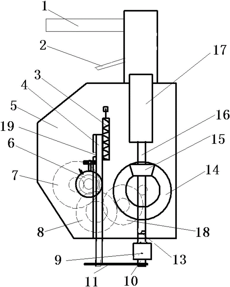
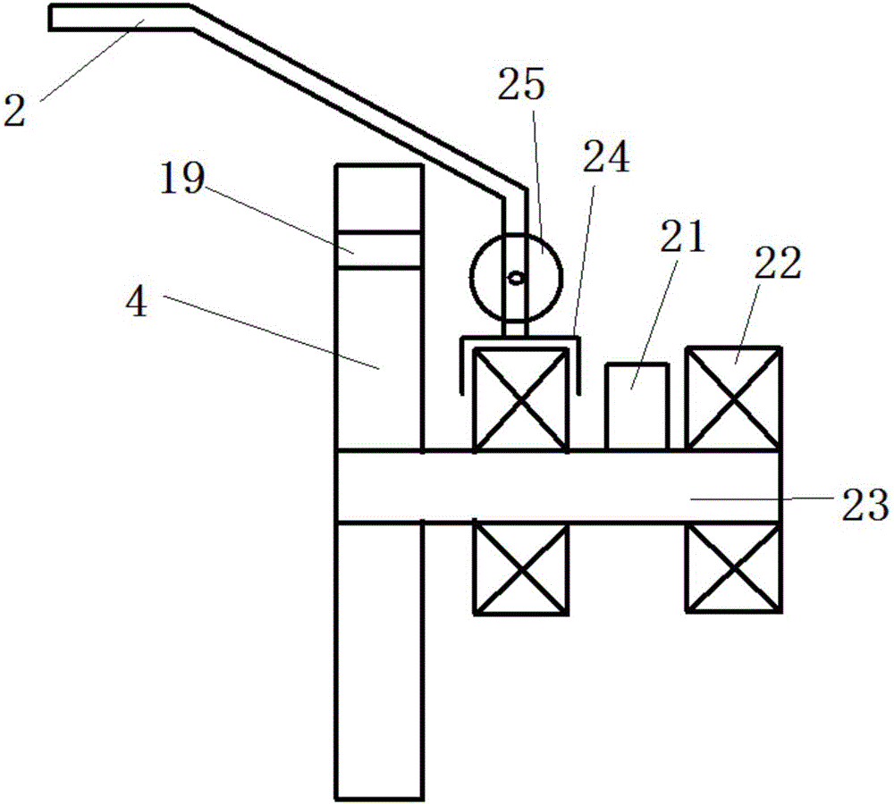
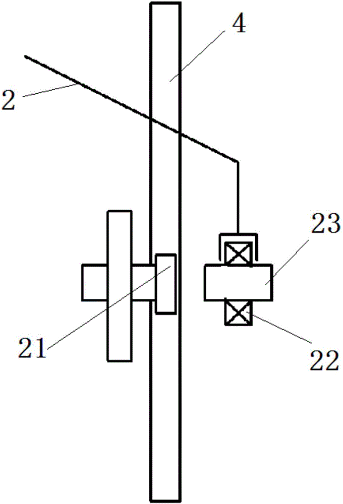
[0016] The present invention is specifically described below in conjunction with accompanying drawing, as figure 1 As shown, the present invention includes a casing 5, a handle 1, and also includes a vibrating device fixed on the casing 5, a gear reduction device, a rack gear, and an engaging device 6; the rack gear includes a rack 4, so The bottom of the tooth bar 4 is fixed with a jaw plate spring 11; the vibrating device includes a driving shaft 16 coaxially rotating with the power shaft 17, and a bevel gear 15 that rotates simultaneously is set on the driving shaft 16, and the driving shaft 16 The lower end of the lower end is provided with a vibrating table 13, and the nail pulling device 9 is provided with a corresponding vibrating table 13. The structure of the vibrating table 13 is as follows: Figure 7 As shown; the gear reduction device includes a gear set composed of a plurality of coaxial large gears and pinions, such as a gear set 14, a gear set 2 18, a gear set 3...


PUM


Abstract

The invention discloses a nail pull-out machine. The nail pull-out machine comprises a vibration device, a gear speed reducer, a rack transmission device and a meshing device which are fixed on a casing. The rack transmission device comprises a rack, and a twine hook plate spring is fixed at the bottom of the rack. The vibration device comprises a driving shaft coaxially rotating along with a power shaft. A bevel gear rotating simultaneously along with the driving shaft is arranged on the driving shaft. A vibration table is arranged at the lower end of the driving shaft, and a nail pull-out device is connected to the lower part of the vibration table. The gear speed reducer comprises a plurality of coaxial gear sets, and the bevel gear is meshed with the gear sets and finally transfers the rotation of the bevel gear to the rack driving gear. The meshing device transfers the rotation of the rack driving gear onto the rack; the meshing device is connected with a shift lever, and the shifting of the meshing device is controlled through the shift lever, and therefore, the meshing of the rack driving gear and the rack is achieved. The nail pull-out machine provided by the invention has the advantages as follows: various driving devices can be adopted; and particularly when an impact drill is taken as the driving device, the nail pull-out machine is reasonable in structure, light in weight, high in efficiency of pulling out nails and suitable for operation by one person.

Description

technical field [0001] The invention relates to the field of engineering machinery, in particular to a nail pulling machine. Background technique [0002] In the construction process in the construction field, many wooden supports and platens are often needed. For fixing these supports and platens, people often use nails. After use, these supports and platens can continue to be used after pulling out the nails; Need some special tools to pull the nails. Chinese patent application number: 201210102630.0 discloses a nail pulling machine. The nail pulling machine includes a frame body on which a motor is fixed. There is an eccentric wheel, the inertia wheel and the eccentric wheel are connected by a connecting shaft, the output end of the motor is connected to the inertia wheel through a belt, the motor drives the inertia wheel and then drives the eccentric wheel to rotate, and a nail pulling device is fixed on the frame. The nail device is connected with the eccentric wheel ...

Claims


Application Information

Patent Timeline
Patent Type & Authority Patents(China)
IPC IPC(8): B25C11/00
Inventor 符文林符强
Owner 符文林
Why Eureka
Try Eureka