
Double-rotor-wing unmanned plane

A UAV and dual-rotor technology, applied in the direction of rotorcraft, motor vehicles, aircraft, etc., can solve the problems of unfavorable control model simplification and increased difficulty, and achieve the advantages of small structural design restrictions, large lift force, and low research cost Effect

Inactive Publication Date: 2014-12-17
NORTHWEST A & F UNIV
View PDF4 Cites 43 Cited by
  • Summary
  • Abstract
  • Description
  • Claims
  • Application Information

AI Technical Summary

Problems solved by technology

This is not conducive to the simplification of the control model, but also increases the difficulty of problem research

Method used


Image

  • Double-rotor-wing unmanned plane
  • Double-rotor-wing unmanned plane
  • Double-rotor-wing unmanned plane

Examples


Embodiment Construction

[0027] The present invention will be described in further detail below in conjunction with the accompanying drawings.

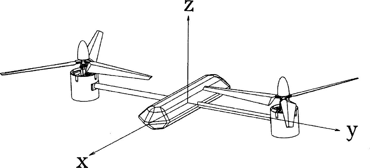
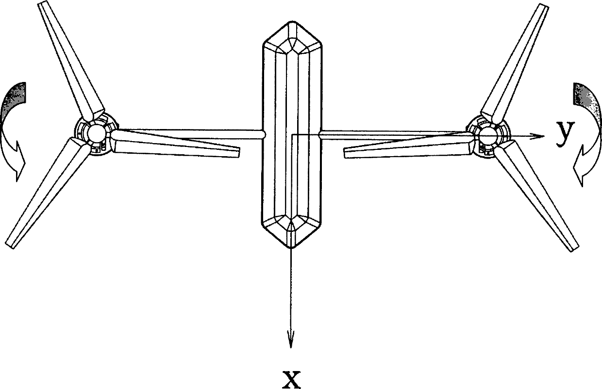
[0028] The present invention is a dual-rotor layout, and its carrier coordinate system is as follows: figure 1 . The rotors are symmetrically distributed on both sides of the fuselage, and the direction of rotation is as follows: figure 2 shown. Its flight control principle is similar to that of a quadrotor UAV. The specific method is: through the control system to control the three angles of the UAV's heading angle, roll angle and pitch angle, the attitude of the UAV can be completely controlled, so that the unmanned The machine as a whole and the horizontal plane generate a controllable inclination angle along the specified direction. The lift force perpendicular to the body of the UAV is therefore decomposed into a lift force perpendicular to the ground and a component force advancing horizontally. In addition to the altitude control, there are four c...


PUM


Abstract

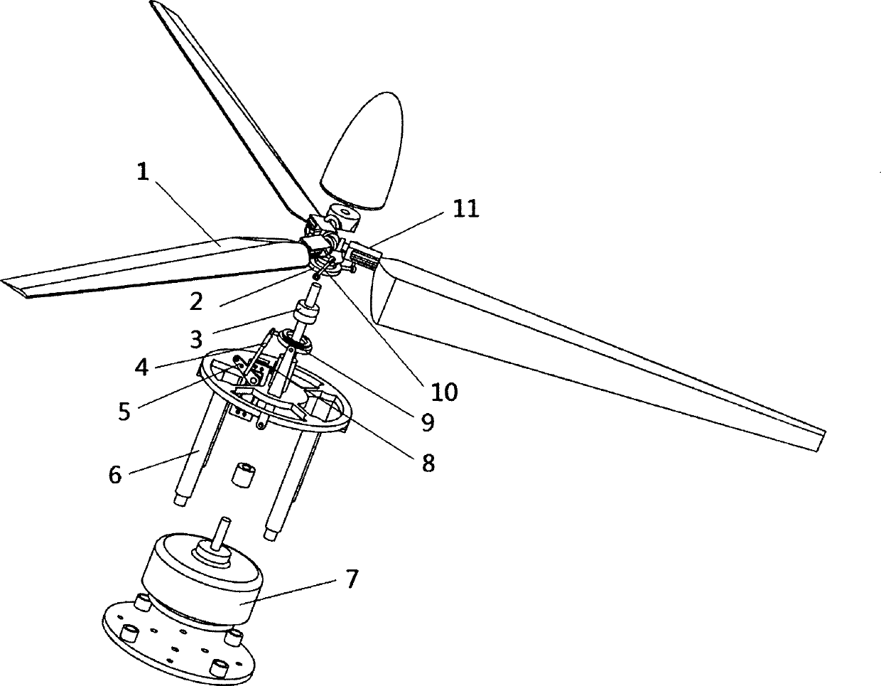
The invention discloses a double-rotor-wing unmanned plane. Flying control on the double-rotor-wing unmanned plane is realized based on a four-rotor-wing unmanned plane flying control principle by designing a single-degree-of-freedom automatic tilter, semi-rigidity rotor wings and a flying control system. The unmanned plane consists of a stander, a plane body, a power bin, rotor wing systems and a rotor wing system support, wherein the plane body is provided with an equipment bin in which a flight posture sensor group, a PID controller, a lithium battery and an electronic speed controller are arranged; the plane body, the power bin and the rotor wing system support are in rigid fixed connection through the stander; a brushless motor and a steering engine are arranged in the power bin; the steering engine drives a pull rod to operate the single-degree-of-freedom automatic tilter and control the rotor wings to periodically change the distance; the angle of the tilter is measured by a potentiometer, so that precise control is facilitated; the rotor wing systems are symmetrically arranged and are positioned on the same horizontal plane; the rotating directions of the rotor wings are opposite, and the rotor wings are mounted on a total distance hinge so as to be mechanically limited to do waving motion. According to the unmanned plane, the operation mechanism is simplified; the flying quality is good; the requirement on the precision of a theoretical model is low, and an extremely high practical value is achieved.

Description

technical field [0001] The invention relates to a dual-rotor UAV, in particular to a non-coaxial dual-rotor UAV using a semi-rigid blade and a single-degree-of-freedom automatic tilter. Background technique [0002] The patent of this invention is a new type of unmanned aerial vehicle designed and proposed based on the flight control principle of four-rotor unmanned aerial vehicle and the principle of periodic pitch change of the conventional helicopter tilter, and the swing of the rotor. The purpose is to solve the problem with a simpler mechanism and a more convenient and easy control system. The problem of complex control and manipulation of the current dual-rotor aircraft. [0003] The existing common non-coaxial dual-rotor aircraft (such as CH-47 "Chinook" helicopter, V-22 "Osprey" tilt rotor aircraft, etc.), its automatic tilter has three degrees of freedom, that is, it moves up and down along the z-axis The control of the collective pitch, the rotation control period...

Claims


Application Information

Patent Timeline
IPC IPC(8): B64C27/08
Inventor 杨福增李长骏秦昊杨鹏
Owner NORTHWEST A & F UNIV
Learn More