Movable bulk material loader

A loader and mobile technology, which is applied in the direction of earth mover/shovel, mechanically driven excavator/dredger, construction, etc., can solve the problems of complex mechanical arm structure, complex loader, poor rigidity, etc., to achieve The effect of large conveying torque, easy transshipment, high strength and rigidity

Inactive Publication Date: 2014-12-17
JINAN JUNXIANG MINING MACHINERY MFG
View PDF5 Cites 7 Cited by
  • Summary
  • Abstract
  • Description
  • Claims
  • Application Information

AI Technical Summary

Problems solved by technology

[0004] Based on this problem, some units have developed a new generation of bulk material loaders, such as a bulk material loader disclosed in Chinese patent 2006100483214, which includes a vehicle body, a conveyor belt, and a reclaiming structure, wherein the reclaiming mechanism is an electric drum. The electric drum grabs the material on the conveyor belt to achieve the purpose of retrieving the material, but the loader with this structure is more complicated because the electric drum is installed on a mechanical arm. The structure of the mechanical arm is complicated and the rigidity is also poor. It is generally suitable for When loading some grains such as wheat, when loading ore, coal and other materials, there will be shaking problems

Method used


Image

  • Movable bulk material loader
  • Movable bulk material loader
  • Movable bulk material loader

Examples


Embodiment 1

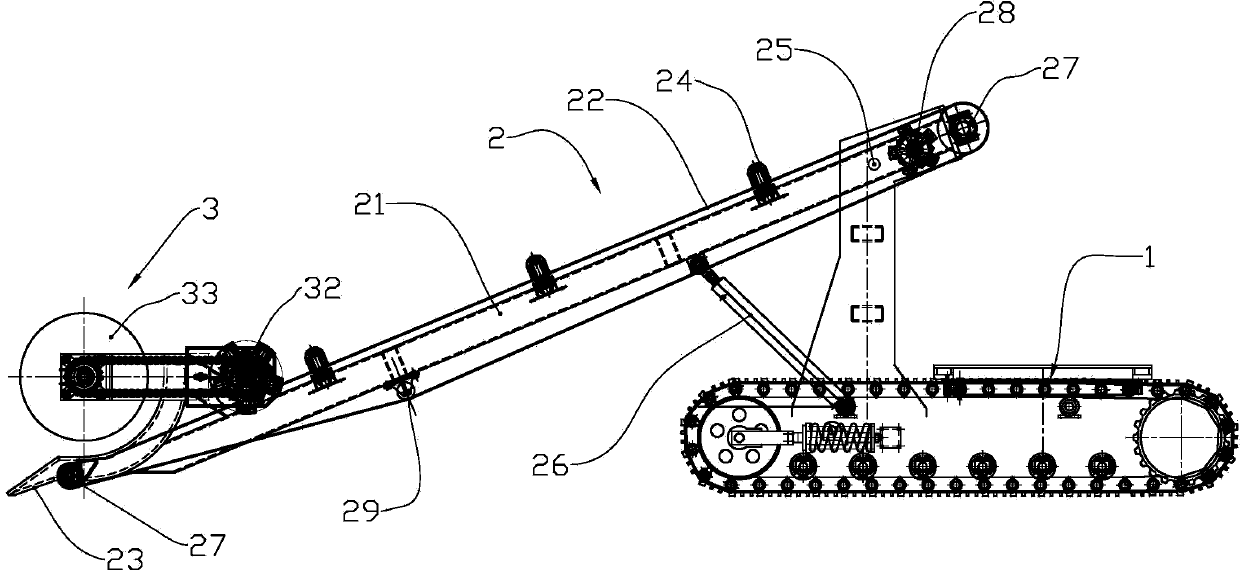
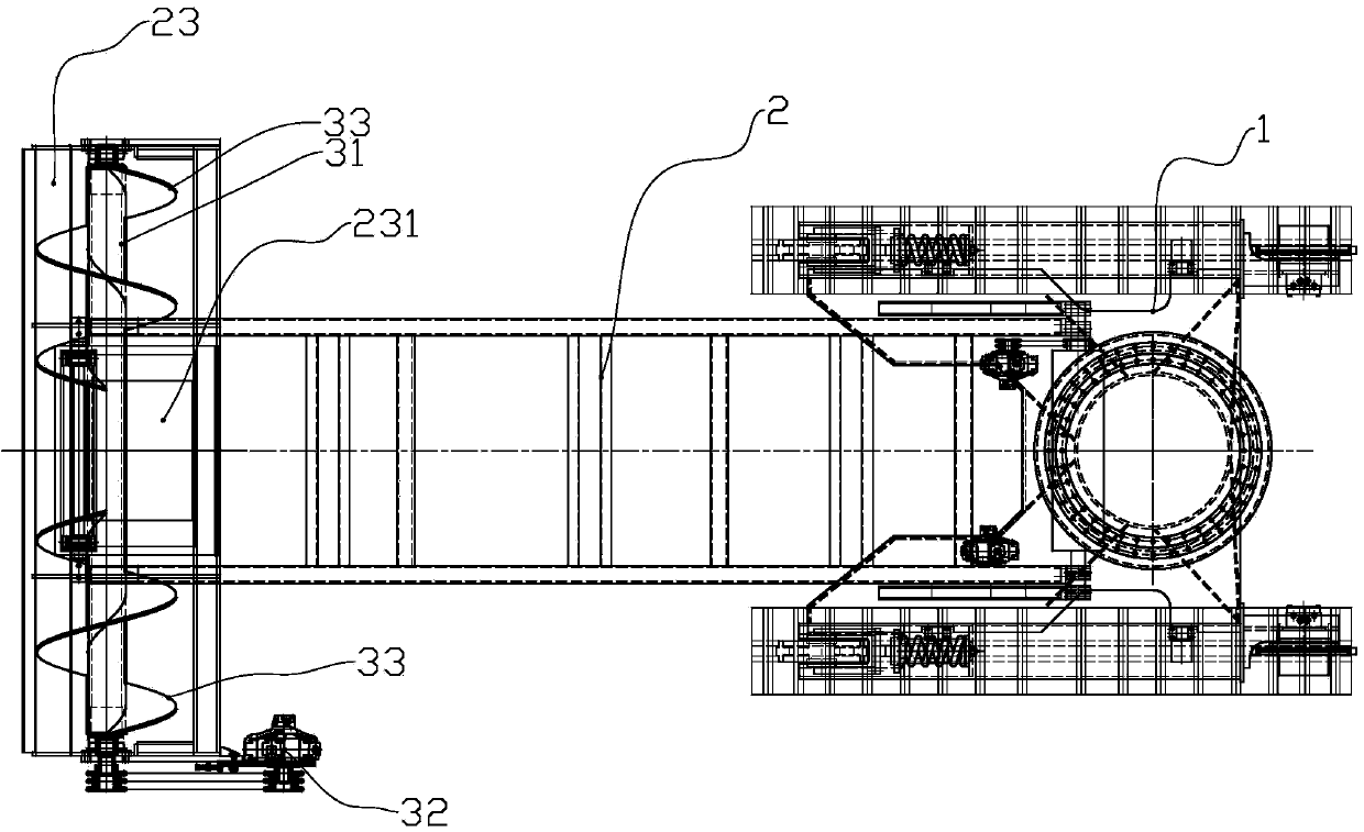
[0025] Such as Figure 1 to Figure 2 As shown, a mobile bulk loader includes three parts: a vehicle body 1, a conveyor belt mechanism 2 and a reclaiming mechanism 3, which will be described in detail below.

[0026] The vehicle body 1 is a crawler-type hydraulically driven vehicle body, which adopts hydraulic drive and has high dynamic performance. The vehicle body is also commonly used in engineering vehicles. For example, a hydraulic crawler excavator is such a body. Install a post upright on the body for mounting the frame.

[0027] The conveyor belt mechanism 2 includes a frame 21, a transmission belt 22, a bucket 23 and an idler roller assembly 24, wherein the frame 21 is a rectangular frame formed by welded section steel, including beams and longitudinal beams, and is the basis for installing the conveyor belt and the reclaiming mechanism. The middle and upper part of the frame 21 is rotatably mounted on the vehicle body through a pin shaft 25 to form a hinge relations...
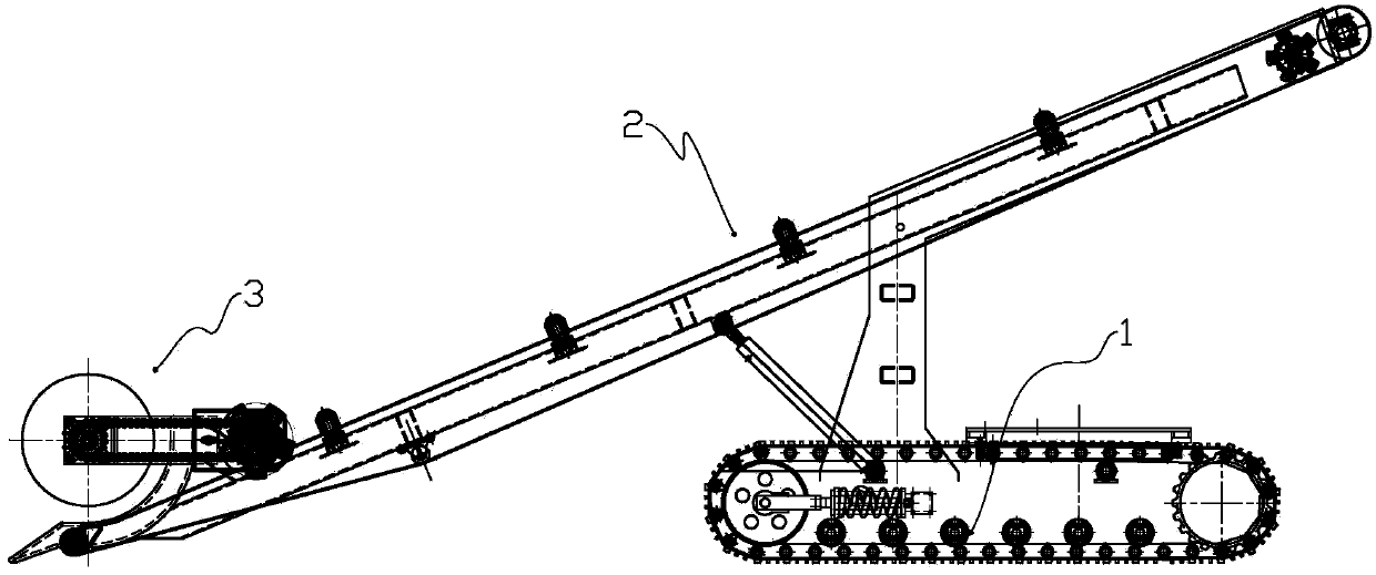
Embodiment 2

[0034] Such as image 3 As shown, the difference from Embodiment 1 lies in the difference in the installation relative positions of the frame and the vehicle body, specifically the difference in the positions of the hinge point and the oil cylinder.


PUM


Abstract

The invention relates to a movable bulk material loader, which comprises a carriage body, a conveyer belt mechanism and a taking mechanism, wherein the conveyer belt mechanism comprises a frame, a drive belt, a bucket and carrier roller assemblies, the frame is rotatably mounted on the carriage body through a pin shaft, an oil cylinder for adjusting the position of the frame by driving is arranged between the frame and the carriage body, the drive belt is driven by a first hydraulic motor, the carrier roller assemblies for supporting the drive belt are arranged on the top of the frame, the bucket is arranged on the front end of the frame, the middle of the bucket is provided with a gap, the drive belt is extended to be under the gap, and screw blades, the helical directions of which are opposite, are respectively arranged with the gap as a symmetry point on both sides of a spindle of the taking mechanism. The movable bulk material loader adopts a full-hydraulic design, traveling, taking and the conveyer belt adopt hydraulic drive, the movable bulk material loader has an automatic taking function, and as the taking mechanism takes material, and the carriage body can constantly feed, so that the act of automatic taking is implemented.

Description

technical field [0001] The solution relates to a mobile loading vehicle, specifically a mobile bulk material loader. Background technique [0002] In mines, docks and other occasions where bulk materials need to be loaded and unloaded, grabs and conveyor belt devices are often used at present, and the grabs are used to grab materials onto the conveyor belt for transportation. [0003] There is an urgent need for a new approach to bulk material loaders. [0004] Based on this problem, some units have developed a new generation of bulk material loaders, such as a bulk material loader disclosed in Chinese patent 2006100483214, which includes a vehicle body, a conveyor belt, and a reclaiming structure, wherein the reclaiming mechanism is an electric drum. The electric drum grabs the material on the conveyor belt to achieve the purpose of retrieving the material, but the loader with this structure is more complicated because the electric drum is installed on a mechanical arm. Th...

Claims


Application Information

Patent Timeline
IPC IPC(8): E02F3/06E02F7/02
Inventor 卢钦波
Owner JINAN JUNXIANG MINING MACHINERY MFG
Why Eureka
Try Eureka