Directional bait feeder

A bait feeder and directional technology, applied in fish farming, application, animal husbandry, etc., can solve problems such as poor uniformity of leakage, increased motor starting resistance, and stuck between the blade and the feeder shell. , to prolong the service life, avoid waste and prevent material jamming

Inactive Publication Date: 2010-07-14
NINGBO UNIV
View PDF5 Cites 18 Cited by
  • Summary
  • Abstract
  • Description
  • Claims
  • Application Information

AI Technical Summary

Problems solved by technology

Among them, the material conveying mechanism mainly has the following structural methods. One is to adopt the material leakage method of the leakage material tray driven by the motor. The uniformity of the material leakage amount of this structure is relatively poor, especially at the beginning of the startup, there will be pouring material leakage, so Can not feed evenly
The second is to use the auger feeding method, but because the auger box has a dead angle of force, the feed will be accumulated and squeezed at the dead angle of the auger to agglomerate, and the agglomerated feed will increase the starting resistance of the motor, even Motor damage due to overload
[0004] The automatic bait feeding machine for fish ponds uses the impeller composed of blades to control the feeding. If the feed particles are slightly large, the feed will easily get stuck between the blades and the feeder shell. The motor is damaged due to excessive resistance; the elastic brush plate set at the end of the blade only reduces the amount of bait broken, and does not improve the feeding situation; moreover, the bait feeding machine needs to manually adjust the feeding amount, which is troublesome The most important thing is that the feeding range of the automatic baiting machine for fish ponds is that the feed is sprinkled from the discharge port to the maximum range of the feed. Because the baiting machine is usually placed on the bank, there is a certain distance from the fish pond. There is no need to sprinkle feed within the distance, and the feed within this distance is wasted in vain

Method used


Image

  • Directional bait feeder
  • Directional bait feeder
  • Directional bait feeder

Examples


Embodiment Construction

[0024] The present invention will be described in further detail below in conjunction with the embodiments of the drawings.

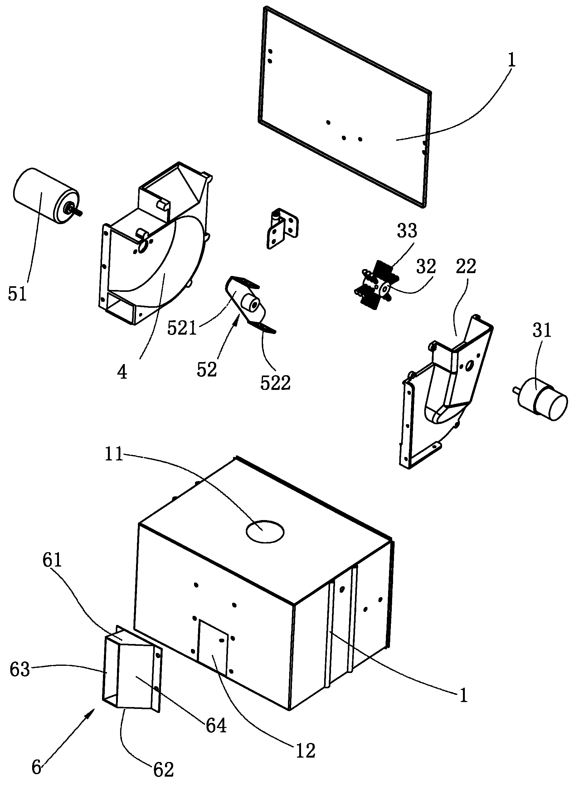
[0025] Such as Figure 1 to Figure 4 As shown, the directional bait-casting machine includes:

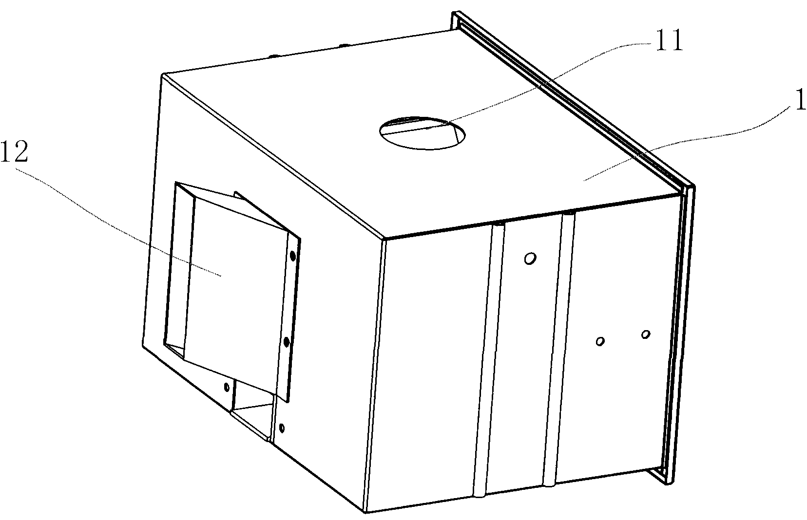
[0026] The housing 1, the housing in this embodiment is rectangular, the top surface of which is provided with a feed inlet 11 for feeding feed into the housing 1, and the front side of the housing 1 is provided with feed for throwing out of the housing 1 的出出口12; For example figure 2 Shown

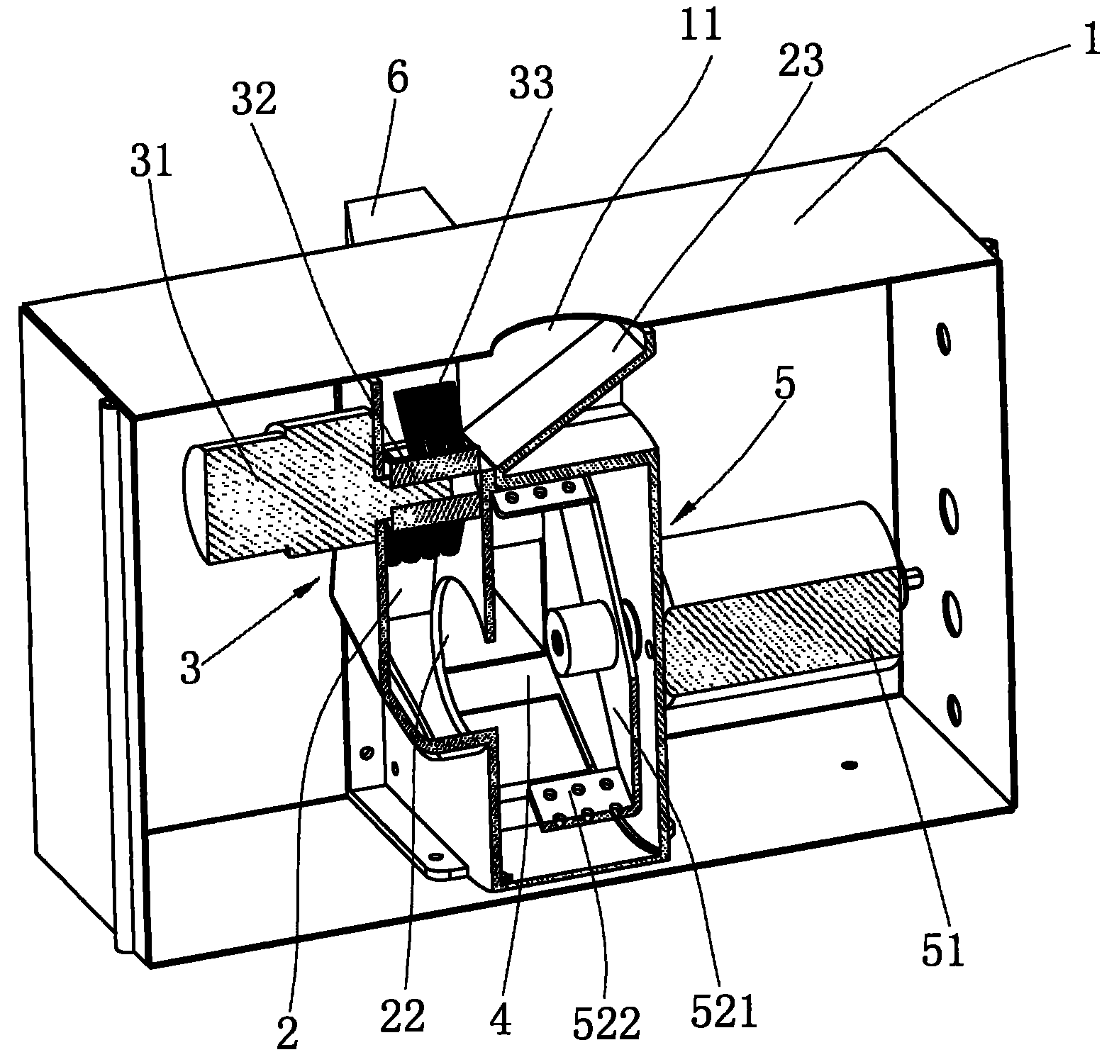
[0027] The guide channel 2 is arranged in the housing 1 at the left side of the feed port 11. A guide channel inlet 21 is provided above the right wall of the guide channel 2, and a guide channel is provided below the right wall of the guide channel 2 Material channel outlet 22; a sliding plate 23 is arranged obliquely below the inlet 11, the upper end of the sliding plate 23 is fixed on the inner wall of the top surface of the shell, the lower end of the sliding plate 23 is s...


PUM


Abstract

The invention relates to a directional bait feeder which comprises a shell. A feeding hole for fodder to enter is arranged on the top surface of the shell. A discharging hole for flinging fodder out of the shell is arranged at one side of the shell which is internally provided with a conveying device and a flinging device, wherein the conveying device bears the fodder entering the shell and conveys the fodder to the next procedure, and the flinging device bears the fodder conveyed by the conveying device and flings the fodder to a set position out of the shell. The directional bait feeder is characterized in that the conveying device comprises a conveying motor with an adjustable speed and a rotating wheel driven by the conveying motor, and the prophetical wall of the rotating wheel is axially and alternately provided with at least two groups of mutually parallel brushes. The invention adopts the brushes to control feeding and can keep feeding evenness and avoid inclined-type discharging during startup to cause blockage. Meanwhile, the deformation amount of the brushes is great, and the sizes of fodder particles are not limited so that the rotating blockage problem can be avoided, and the feeding amount can be adjusted by adjusting the rotating speed of the conveying motor.

Description

Technical field [0001] The invention relates to a feed feeding device, in particular to a bait feeding machine capable of directional feeding feed. Background technique [0002] The existing bait-casting machine usually includes a feed box, a feeding mechanism and a ejection mechanism. Among them, the conveying mechanism mainly has the following structural methods. One is the method of leaking material by the leakage tray driven by the motor. The uniformity of the leakage amount of this structure is poor, especially the dumping leakage occurs at the beginning of the startup. Can not feed evenly. The second is to use the auger conveying method, but because the auger box has a dead corner of force, the dead corner of the auger will cause the feed to accumulate and squeeze and agglomerate. These agglomerated feed will increase the starting resistance of the motor, even The motor is damaged due to overload. The centrifugal conveying method is used. The centrifugal conveying usuall...

Claims


Application Information

Patent Timeline
Patent Type & Authority Applications(China)
IPC IPC(8): A01K61/02
Inventor 葛英辉
Owner NINGBO UNIV
Why Eureka
Try Eureka