Simple buried installation fixed bracket and installation method thereof

A fixed frame and simple technology, applied to the simple buried installation fixed frame and its installation field, can solve the problems of high installation difficulty, low installation efficiency, large labor cost, etc., to simplify installation steps, improve installation efficiency, and reduce installation. cost effect

Inactive Publication Date: 2014-12-17
袁见见
View PDF6 Cites 5 Cited by
  • Summary
  • Abstract
  • Description
  • Claims
  • Application Information

AI Technical Summary

Problems solved by technology

[0002] Traditional utility poles, street light poles, flower signboards, signboards, advertising light boxes, etc. are installed by digging a large hole in the ground, and then supporting the utility poles, street light poles, flower signboards, signboards, and advertising light boxes The rod body is inserted into the dug big pit, and then fixed and buried by pouring cement into the big pit (it takes 4-5 days for the cement to be completely stable and air-dried). After the cement is dry, the rod body must be supported for anti-fixation Install an iron plate at the contact point with the concrete ground, and then install fixing bolts on the iron plate. When this installation method encounters large-scale building piling nearby or encounters natural disasters and earthquakes, these utility poles, street light poles, flower signs, Signs, advertising light boxes, etc. are very easy to collapse and hurt people due to unstable foundations, and the safety is poor
The traditional installation met

Method used


Image

  • Simple buried installation fixed bracket and installation method thereof
  • Simple buried installation fixed bracket and installation method thereof
  • Simple buried installation fixed bracket and installation method thereof

Examples


Embodiment Construction

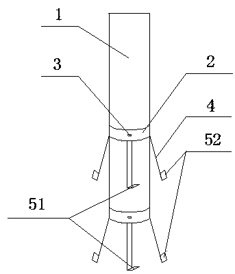
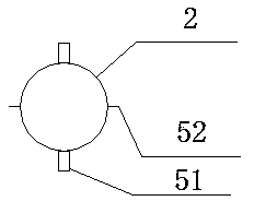
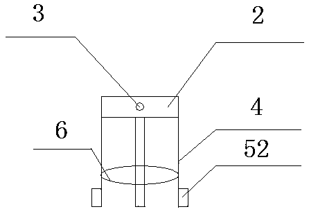
[0019] In this example, refer to Figure 1 to Figure 8 As shown, a simple buried installation fixture and its installation method include a column body 1, and a mounting ring 2 set on the outside of the column body 1, and a mounting hole 3 set in the middle of the side of the mounting ring 2, and setting The support rod 4 on the lower edge of the mounting ring 2, and the upper and lower fixed feet 51 or rotating fixed feet 52 arranged at the end of the support rod 4.

[0020] Wherein, each support rod 4 bounces at an angle of 10° to 60°, and multiple support rods 4 form a plurality of triangles with different angles when they bounce off, so as to ensure that the column 1 is firmly buried in the soil.

[0021] Wherein, the shape of the upper and lower fixed feet 51 is placed horizontally and fixedly connected with the support rod 4, so as to prevent the cylinder 1 from being lifted up by people, which is safe and stable; the shape of the rotating fixed foot 52 is placed vertica...


PUM


Abstract

The invention discloses a simple buried installation fixed bracket and an installation method thereof. The simple buried installation fixed bracket comprises a column body, an installation ring which sleeves the column body, an installation hole which is formed in a middle position of the side surface of the installation ring, support rods which are arranged on the lower end edge of the installation ring, and upper and lower fixing legs or rotating fixing legs which are arranged on the tail ends of the support rods. By adopting the simple buried installation fixed bracket and the installation method thereof, simplicity in installation is realized, the manpower and material resources can be saved, the installation procedures can be simplified, the installation time can be saved, the installation efficiency can be improved, and the installation cost can be reduced; the support rod is recyclable, so that the recycling of the resources is realized, the construction area is reduced, energy conservation and environmental protection can be realized, flexibility in installation can be realized, upward unplugging, sinking and rotation can be prevented, the firmness degree is high, safety is high, and simplicity in maintenance can be realized.

Description

technical field [0001] The invention relates to an installation fixture, in particular to a simple buried installation fixture and an installation method thereof. Background technique [0002] Traditional utility poles, street light poles, flower signboards, signboards, advertising light boxes, etc. are installed by digging a large hole in the ground, and then supporting the utility poles, street light poles, flower signboards, signboards, and advertising light boxes The rod body is inserted into the dug big pit, and then fixed and buried by pouring cement into the big pit (it takes 4-5 days for the cement to be completely stable and air-dried). After the cement is dry, the rod body must be supported for anti-fixation Install an iron plate at the contact point with the concrete ground, and then install fixing bolts on the iron plate. When this installation method encounters large-scale building piling nearby or encounters natural disasters and earthquakes, these utility pole...

Claims


Application Information

Patent Timeline
IPC IPC(8): E04H12/22
Inventor 袁见见
Owner 袁见见
Why Eureka
Try Eureka