Heat dissipation device

A heat sink and heat dissipation fin technology, applied in the field of lighting, can solve the problems of low heat dissipation efficiency and low wind energy utilization rate of fans, etc., and achieve the effect of improving heat dissipation efficiency and wind energy utilization rate

Active Publication Date: 2014-12-17
SHENZHEN OCEANS KING LIGHTING ENG CO LTD +1
View PDF7 Cites 12 Cited by
  • Summary
  • Abstract
  • Description
  • Claims
  • Application Information

AI Technical Summary

Problems solved by technology

[0003] However, in this heat dissipation structure, most of the airflow generated by the fan flows directly int

Method used


Image

  • Heat dissipation device
  • Heat dissipation device
  • Heat dissipation device

Examples


Embodiment Construction

[0018] The following will clearly and completely describe the technical solutions in the embodiments of the present invention with reference to the accompanying drawings in the embodiments of the present invention. Obviously, the described embodiments are only some, not all, embodiments of the present invention. Based on the embodiments of the present invention, all other embodiments obtained by persons of ordinary skill in the art without creative efforts fall within the protection scope of the present invention.

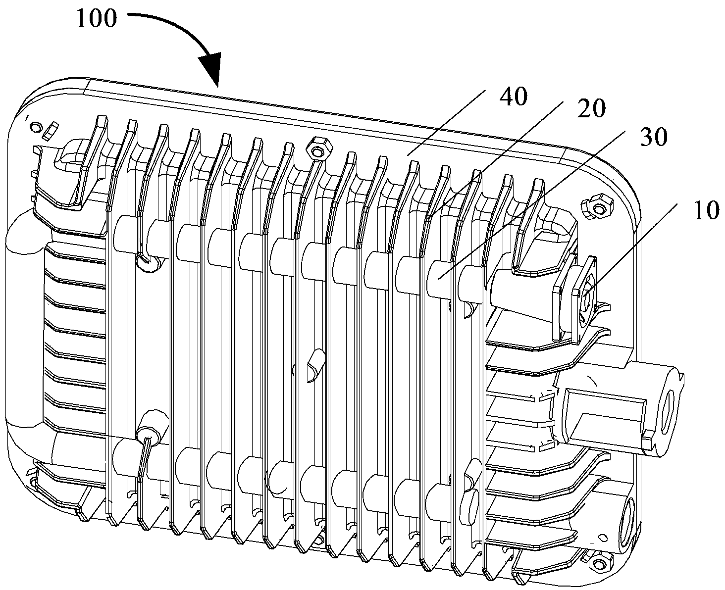
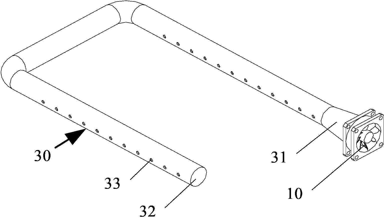
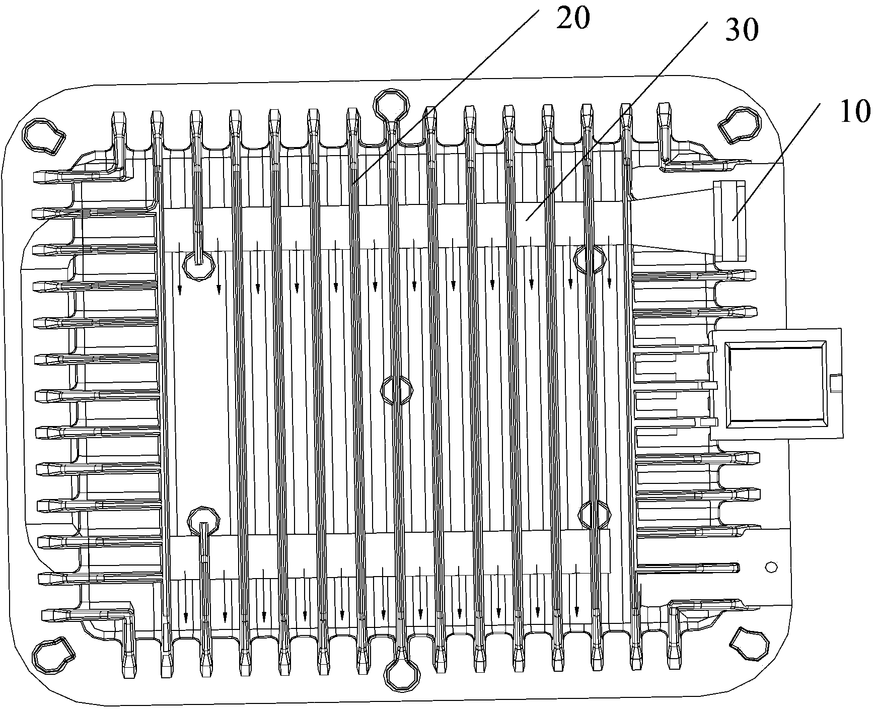
[0019] Embodiments of the present invention will be described below with reference to the accompanying drawings. see figure 1 , is a schematic structural diagram of the heat sink 100 in the embodiment of the present invention. In this embodiment, the heat sink 100 is used on the outer wall of the housing 40 of the lamp, so as to dissipate heat from the housing 40 . The heat sink 100 includes a fan 10 , a plurality of heat dissipation fins 20 arranged in parallel,...


PUM


Abstract

The invention discloses a heat dissipation device. The heat dissipation device comprises a fan, a plurality of cooling fins arranged in parallel, and an air guiding pipe penetrating through the cooling fins. One end of the air guiding pipe is communicated with the fan. A plurality of air holes are formed in the air guiding pipe. Each air hole is located between the corresponding two adjacent cooling fins. In the heat dissipation device, whole air flow generated by the fan flows to the air guiding pipe and is sprayed out only through the air holes, and therefore the wind energy utilization rate of the fan is increased. In addition, the heat dissipation structure that the air guiding pipe penetrates through the cooling fins is adopted, and therefore the heat dissipation efficiency of the heat dissipation device is improved.

Description

technical field [0001] The invention relates to the lighting field, in particular to a radiator. Background technique [0002] In order to remove heat accumulated on the lamp, a common cooling method is to install a heat sink on the lamp. The heat dissipation device commonly used at present comprises heat dissipation fins and a fan, and the heat on the lamp is conducted into the air through the heat dissipation fins. The fan is used to generate airflow, which accelerates the conduction of heat from the cooling fins to the air, thereby improving the cooling efficiency. [0003] However, in this heat dissipation structure, most of the airflow generated by the fan flows directly into the air, so the utilization rate of wind energy of the fan is low, and the heat dissipation efficiency is low. Contents of the invention [0004] The technical problem to be solved by the present invention is to provide a radiator that can improve the utilization rate of wind energy and the hea...

Claims


Application Information

Patent Timeline
IPC IPC(8): F21V29/02
Inventor 周明杰刘先斌
Owner SHENZHEN OCEANS KING LIGHTING ENG CO LTD
Why Eureka
Try Eureka