Measuring distance adjustable OTA (over-the-air) test darkroom

A technology for measuring distance and anechoic chamber, applied in the field of antenna OTA, it can solve the problems of small measurement distance, low terminal conduction sensitivity, large space loss, etc., and achieve the effect of stable and reliable testing.

Inactive Publication Date: 2014-12-17
SHENZHEN SINOPOW COMM TECH
View PDF8 Cites 16 Cited by
  • Summary
  • Abstract
  • Description
  • Claims
  • Application Information

AI Technical Summary

Problems solved by technology

[0006] 5GHz high-frequency band, the wavelength is short, the required measurement distance is small, and the space loss at the same distance is large
In the measurement of these high-frequency bands, the space loss is very large, and the conduction sensitivity of the terminal itself is not high, while the high-frequency antenna has strong directi...

Method used


Image

  • Measuring distance adjustable OTA (over-the-air) test darkroom
  • Measuring distance adjustable OTA (over-the-air) test darkroom
  • Measuring distance adjustable OTA (over-the-air) test darkroom

Examples


Embodiment 1

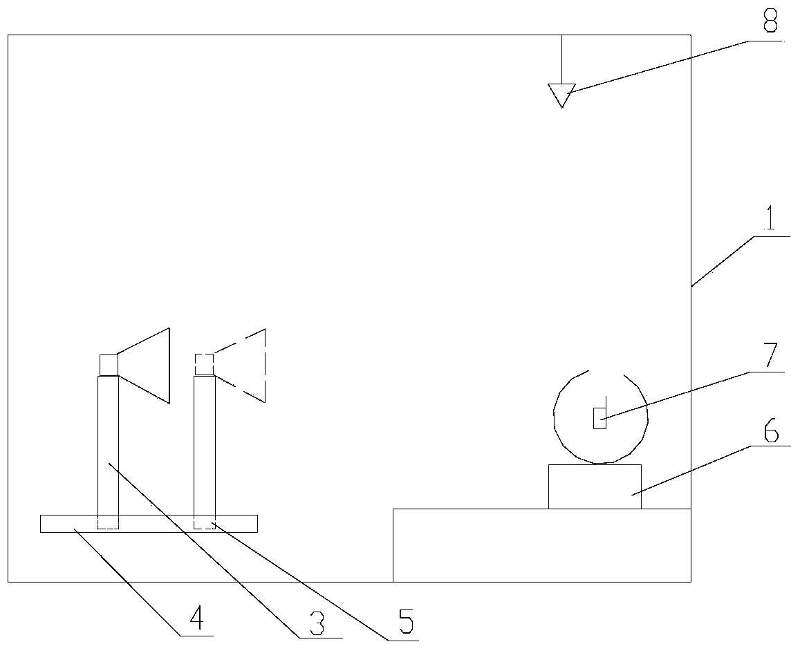
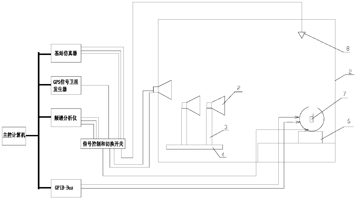
[0023] Example 1, such as figure 1 , image 3 and Figure 4 Shown:

[0024] The invention is a testing darkroom applied to mobile phone antenna OTA testing.

[0025] In order to overcome the problems existing in the prior art, in the present embodiment, the present invention includes a test darkroom body 1 and a measurement turntable 6 and a darkroom communication antenna 8 arranged in the darkroom body, and the test body 1 is provided with a Measuring antenna 2 with repositioning. The structures, installation methods and positions of the test darkroom body 1 , the measuring turntable 6 arranged in the darkroom body and the darkroom communication antenna 8 in the present invention are all the same as those of the prior art.

[0026] In order to achieve the purpose of adjusting the position of the test antenna in the present invention, the measurement antenna 2 is arranged on a measurement antenna bracket 3 in this embodiment. The measurement antenna bracket 3 includes a f...

Embodiment 2

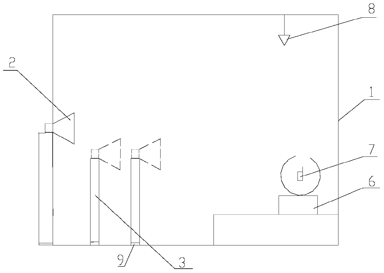
[0040] Example 2, figure 2 Shown:

[0041] In this embodiment, the technical solution of setting multiple test points corresponding to the test turntable in the darkroom is adopted to satisfy different test distances.

[0042] A plurality of measurement antenna brackets 3 are arranged in the measurement darkroom body 1 , and the plurality of measurement antenna brackets 3 are respectively fixed on a plurality of distance points corresponding to the measurement turntable 6 . The distance point 9 refers to a specific position of the test antenna corresponding to the test turntable. In layman's terms, the measurement antenna bracket 3 is fixed at multiple positions in the measurement chamber body 1, so that the distance from each distance point to the test turntable is different, so it can meet the test requirements of different frequency ranges.

[0043] 1-20 measuring antenna brackets 3 are arranged in the measuring darkroom body 1, and are respectively fixed on the distance p...


PUM


Abstract

The invention relates to a measuring distance adjustable OTA (over-the-air) test darkroom and belongs to the technical field of mobile phone antenna OTA, namely over-the-air transmission test devices. The test darkroom comprises a test darkroom body as well as a measuring turntable and a darkroom communication antenna arranged in the test darkroom body. The test darkroom is characterized in that position-changeable measuring antennas are arranged in the test darkroom body, and each measuring antenna is arranged on one measuring antenna support; each measuring antenna support comprises a supporting foot, a supporting rod and an antenna fixing device; each supporting foot is located at the lower end of each supporting rod, and each antenna fixing device is arranged on the corresponding supporting rod. The defect that the position, corresponding to the measuring antennas, of a measuring turntable in an OTA test darkroom in the prior art is fixed and unchanged is overcome, positional changing of the measuring antennas in the test darkroom is realized, the most appropriate measuring distance is provided for each operating frequency and each communication system so as to ensure smoothness in testing, and most stable and reliable testing is provided.

Description

Technical field: [0001] The invention relates to an OTA test darkroom with adjustable measuring distance, which belongs to the technical field of mobile phone antenna OTA, that is, a test device for air transmission. Background technique: [0002] The OTA test chamber is a specially designed device for testing the air transmission parameters of mobile phone antennas. In the existing OTA test chamber, the measurement antenna is fixed. Once the antenna darkroom is built, the distance between the measurement turntable where the terminal to be tested is placed and the measurement antenna in the darkroom is fixed. [0003] However, today's terminals support more and more communication systems, the frequency range is wider and wider, and the frequency band to be measured is wider and wider. For example, the working frequency band of 4G LTE (Long Term Evolution) is from 700MHz to 2.6GHz, WIFI has a working frequency band of 2.4GHz / 5GHz, and GPS is 1.575GHz. Therefore, the darkro...

Claims


Application Information

Patent Timeline
IPC IPC(8): G01R31/00G01R1/04
Inventor 白剑
Owner SHENZHEN SINOPOW COMM TECH
Why Eureka
Try Eureka