a window cleaning machine

A window cleaning machine and head cleaning technology, which is applied to window cleaning, cleaning equipment, household appliances, etc., can solve problems such as dirty shells, poor water and air separation, and affect the normal operation of window cleaning machines, achieving convenience Card connection, prevent sewage from being sucked into the suction port

Active Publication Date: 2017-02-15
ZHANGJIAGANG CHUANGJI MACHINERY MFG
View PDF5 Cites 0 Cited by
  • Summary
  • Abstract
  • Description
  • Claims
  • Application Information

AI Technical Summary

Problems solved by technology

[0004] The disadvantage of the water-air separation device in the above-mentioned window cleaning machine is: since the water outlet end and the air suction port at the bottom of the water suction port directly extend into the water-air separation chamber, and the air mixed with sewage can flow from the front and back of the water-retaining air plate. The rear side enters the water-air separation chamber at the same time, which makes the effect of water-air separation not good. During work, water is often sucked into the induced draft fan of the suction device, which will not only dirty the shell, but also affect the cleaning of the window in severe cases. normal operation of the machine
[0005] In addition, the design of the sewage collection box of many window cleaning machines is unreasonable. During the window cleaning process, due to the excessive forward or backward tilt angle of the window cleaning machine, the sewage will flow back from the sewage collection box, and finally from the window cleaning machine. Outflow from the suction port of the head

Method used


Image

  • a window cleaning machine
  • a window cleaning machine
  • a window cleaning machine

Examples


Embodiment Construction

[0020] The present invention will be described in further detail below through specific embodiments and accompanying drawings.

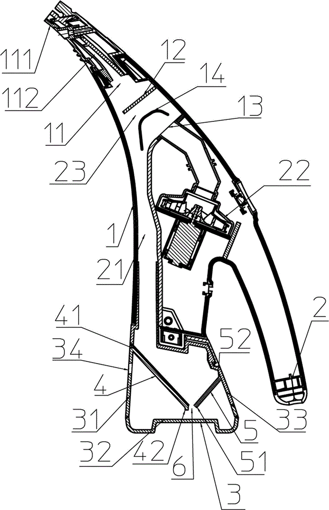
[0021] A window cleaning machine, such as figure 1 As shown, it includes a housing 1, the rear of the housing 1 is provided with a handle 2, the top of the front of the housing 1 is equipped with a wipe head 111 with an eraser strip, the water suction port 112 of the wipe head 111 is connected with the water on the top of the housing The air inlet 11 communicates, and a sewage collection box 3 is installed on the bottom of the housing 1. A water channel 21 capable of introducing water into the sewage collection box 3 is provided between the water gas inlet 11 and the sewage collection box 3. The water channel 21 is located at the bottom of the housing 1. The front part is also provided with a water-air separation chamber 23 between the water channel 21 and the water-air inlet 11, and a suction device 22 is also provided in the housing 1, and the air ...


PUM


Abstract

The invention discloses a window-cleaning machine which comprises a shell, wherein a handle is arranged on the rear part of the shell; a cleaning head is mounted above the shell; a water suction port of the cleaning head is communicated with a water-air inlet of the shell; a sewage collecting box is mounted on the lower part of the shell; a water channel is arranged between the water-air inlet and the sewage collecting box; a water-air separating cavity is arranged between the water channel and the water-air inlet; an air absorbing device is arranged in the shell; an air absorbing port of the air absorbing device is arranged on a lateral wall of the water-air separating cavity; a front baffle is arranged in the water-air separating cavity; a water-air separating plate is arranged between the front baffle and the air absorbing port; a water-stopping plate is arranged in the sewage collecting box; the front end of the water-stopping plate is jointed with an inside wall at the front end of the sewage collecting box; the left and right sides of the water-stopping plate are jointed with left and right inside walls of the sewage collecting box; a clearance exists between the rear end of the water-stopping plate and the inner bottom surface of the sewage collecting box; the front end of the water-stopping plate is not lower than the rear end. The window-cleaning machine can be used for efficiently separating water from air, can prevent water from being absorbed into the air absorbing port and also can prevent water from flowing backwards out of the sewage collecting box.

Description

technical field [0001] The invention relates to the field of household equipment, in particular to a window cleaning machine capable of effectively separating water and air and preventing backflow of sewage. Background technique [0002] The window cleaning machine is mainly used to wipe the glass. The structure of the window cleaning machine mainly includes: a housing, a handle is arranged on the rear side of the housing, a wiping head with an eraser strip is arranged on the top of the housing, and a wiping head is set in the wiping head. There is a water suction port, and the water outlet end of the bottom of the water suction port extends into the water-air separation chamber in the shell. A sewage collection box is installed at the bottom of the shell. The water channel of the sewage collection box is also provided with a suction device that can suck the sewage during wiping into the water-air separation chamber from the water suction port in the housing. After the air ...

Claims


Application Information

Patent Timeline
Patent Type & Authority Patents(China)
IPC IPC(8): A47L1/06
Inventor 沈兴祥
Owner ZHANGJIAGANG CHUANGJI MACHINERY MFG
Why Eureka
Try Eureka