A balloon fatigue test device

A technology of fatigue testing and balloons, applied in the direction of stents, etc., can solve problems such as expensive and complex structures

Active Publication Date: 2016-07-06
ESSEN TECH (BEIJING) CO LTD
View PDF11 Cites 0 Cited by
  • Summary
  • Abstract
  • Description
  • Claims
  • Application Information

AI Technical Summary

Problems solved by technology

[0003] Existing balloon fatigue testing devices such as the "HPT-1000 Water Pressure Testing Machine" manufactured by INTERFACE are complex in structure and expensive

Method used


Image

  • A balloon fatigue test device
  • A balloon fatigue test device
  • A balloon fatigue test device

Examples


Embodiment Construction

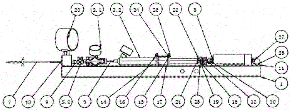
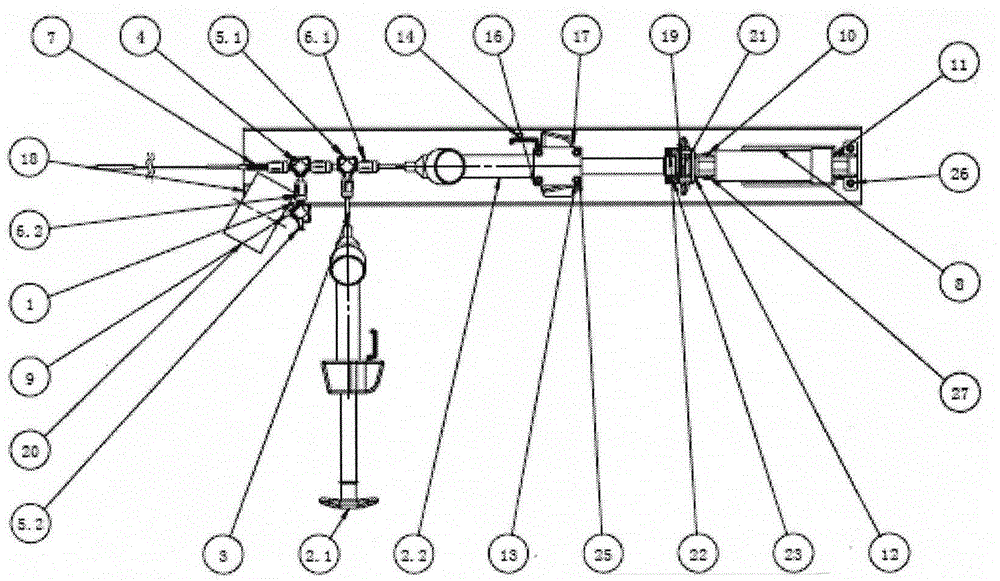
[0028] first press figure 1 , figure 2 As shown, it consists of machine base 1, balloon infusion pump 2.1, balloon expansion pump 2.2, hose 3, three-way 4, three-way valve 5.1 and 5.2, special joints 6.1 and 6.2, electric pusher 8, Luer joint 9 , Pin shaft 10, front support 11, rear support 12, stud 13, limit column 14, upper connection block 15, pressure plate 16, pump backing plate 17, valve seat 18, lower connection block 19, intelligent pressure A balloon fatigue testing device composed of the controller 20 and the standard parts 21-26 is assembled and connected; the connection is ensured firmly, and the system is reliable and leak-free at ≥ 30 atm.

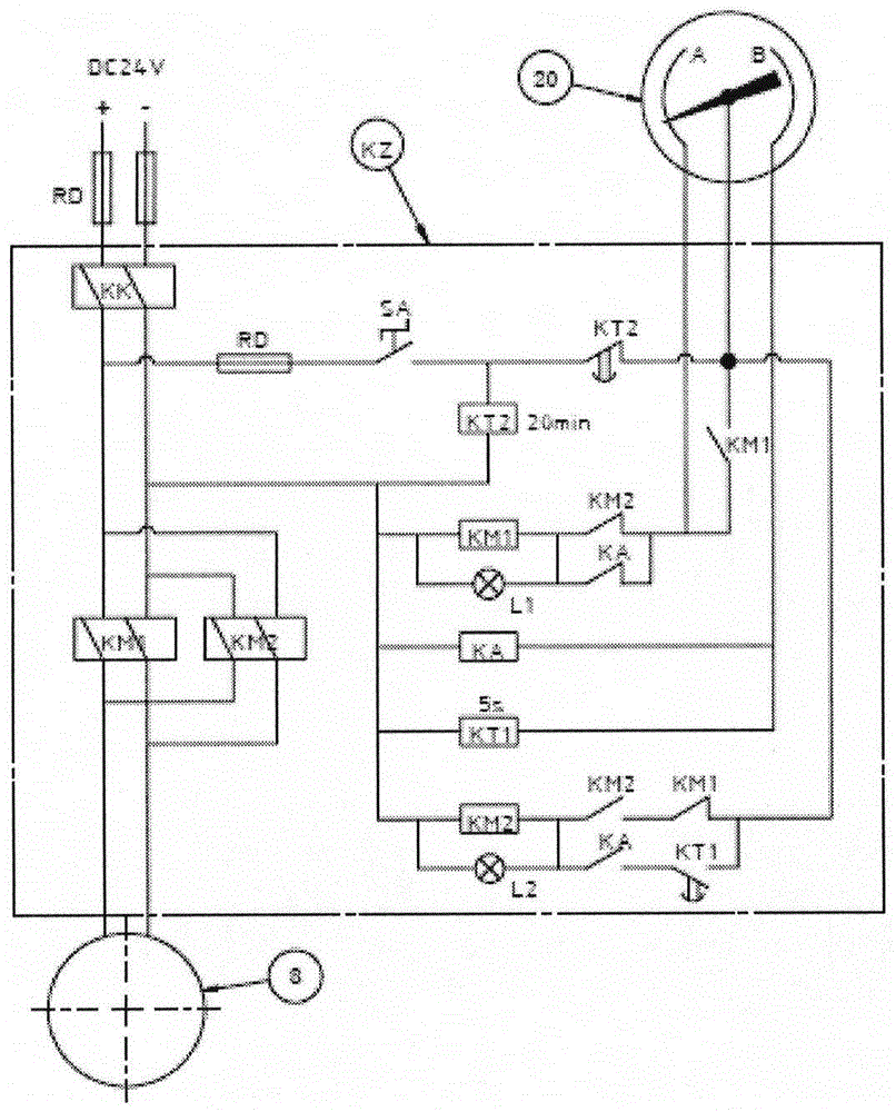
[0029] according to image 3 0~24V adjustable power supply, control box KZ, air switch KK, rotary switch SA, relay KM1, relay KM2, intermediate relay, delay on relay KT1, delay off relay KT2, indicator light L1 (red), The indicator light L2 (green), fuse RD, etc. are assembled and connected.

[0030] Connect the electric...


PUM


Abstract

A balloon fatigue testing device consists of a machine base (1), a balloon infusion pump (2.1), a balloon expansion pump (2.2), a hose (3), a three-way (4), a three-way valve (5.1) and ( 5.2), special connectors (6.1) and (6.2), electric pusher (8), Luer connector (9), pin shaft (10), front support (11), rear support (12), double-ended screw Column (13), limit column (14), upper connection block (15), pressure plate (16), pump backing plate (17), valve seat (18), lower connection block (19), intelligent pressure controller (20 ) and standard parts (21-26); the electric push device (8) pushes the piston rod of the balloon dilation pump (2.2) to reciprocate, so as to realize the fatigue test of a balloon catheter delivery system (7).

Description

Technical field: [0001] The invention relates to a test device for a vascular stent balloon catheter delivery system, in particular to a balloon fatigue test device. Background technique: [0002] The existing stent balloon catheter delivery system, as a tool for stent delivery, plays an extremely important role in the stent delivery process; under the guidance of the guide catheter and guide wire, the stent is delivered to the lesion, The whole process until the balloon expands the stent and withdraws it. During the operation, the performance of the balloon catheter delivery system directly affects the success or failure of the operation. Since there are different thickness and very curved blood vessels in the human body, and severe diseased blood vessels are accompanied by calcification, it is necessary for the balloon catheter delivery system to have a very small outer diameter, good flexibility, and strong pushability to facilitate passage through tortuous The diseased...

Claims


Application Information

Patent Timeline
Patent Type & Authority Patents(China)
IPC IPC(8): A61F2/95
Inventor 孟春旺赵迎红褚洋郭承年
Owner ESSEN TECH (BEIJING) CO LTD
Why Eureka
Try Eureka