
Pneumatic clamping springing machine

A technology of clipping machine and spring clips, applied in metal processing, metal processing equipment, manufacturing tools, etc., can solve the problems of different quality of spring clips, difficult production inspection, low production efficiency, etc., to achieve good product quality and simple operation. , the effect of high work efficiency

Active Publication Date: 2014-12-24
永春县产品质量检验所福建省香产品质量检验中心国家燃香类产品质量监督检验中心福建
View PDF7 Cites 2 Cited by
  • Summary
  • Abstract
  • Description
  • Claims
  • Application Information

AI Technical Summary

Problems solved by technology

[0003] Although the volume of the spring clip is small, due to the irregular volume of the torsion spring, it is very difficult to install the torsion spring between the two clips of the spring clip during production. The existing production process generally uses manual operations to press the torsion spring into the The two clips of the spring clip are used for fixing. This method has low production efficiency, and the quality of the spring clips produced is different, so it is difficult to carry out unified production inspection. Moreover, when the torsion spring is installed, the torsion spring is prone to spring off, which is easy to damage the operation. or low production safety

Method used


Image

  • Pneumatic clamping springing machine
  • Pneumatic clamping springing machine
  • Pneumatic clamping springing machine

Examples


Embodiment Construction

[0020] The present invention will be further described below in conjunction with accompanying drawing:

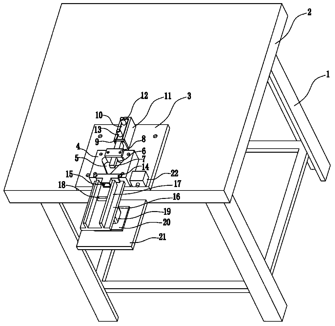
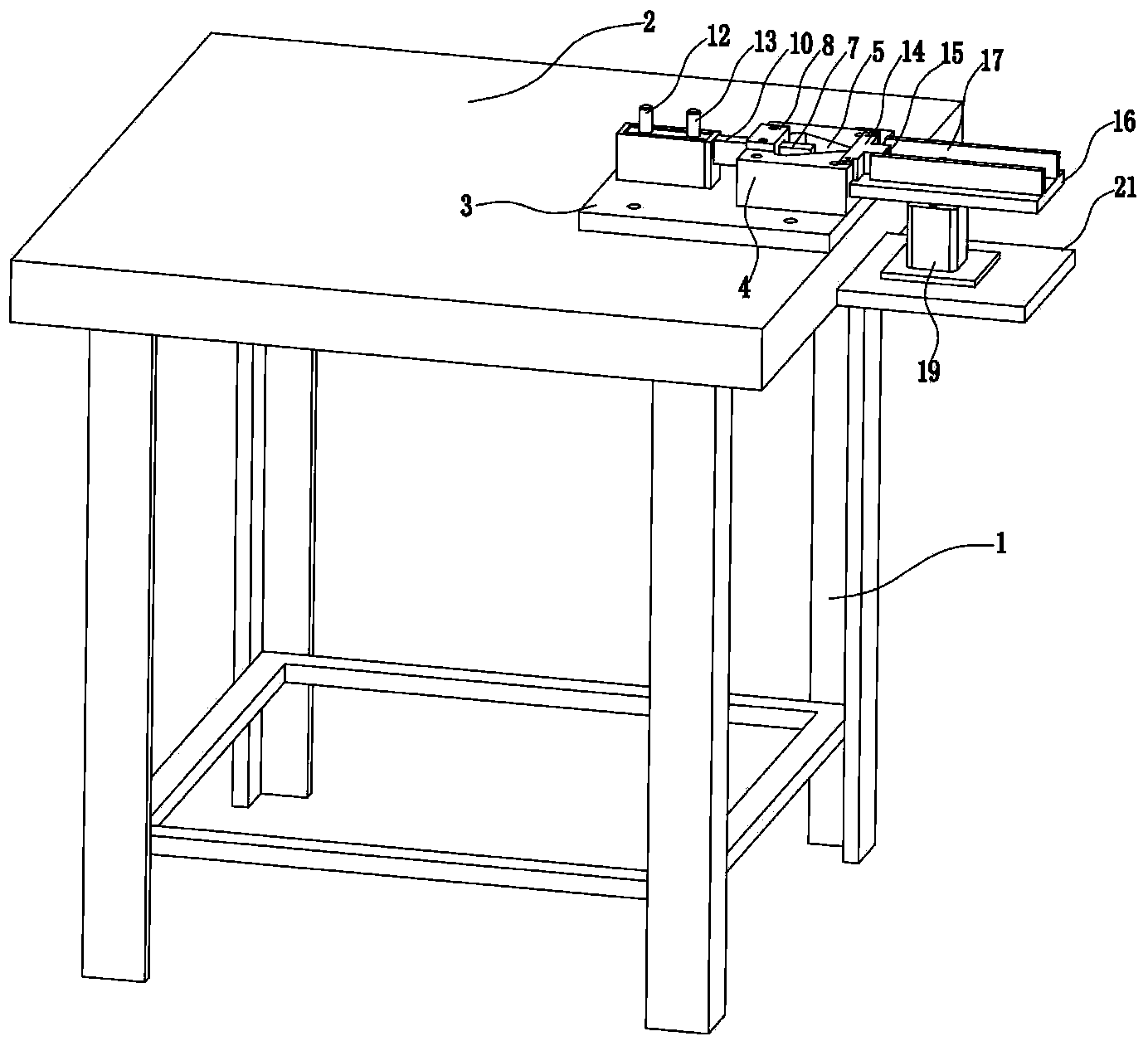
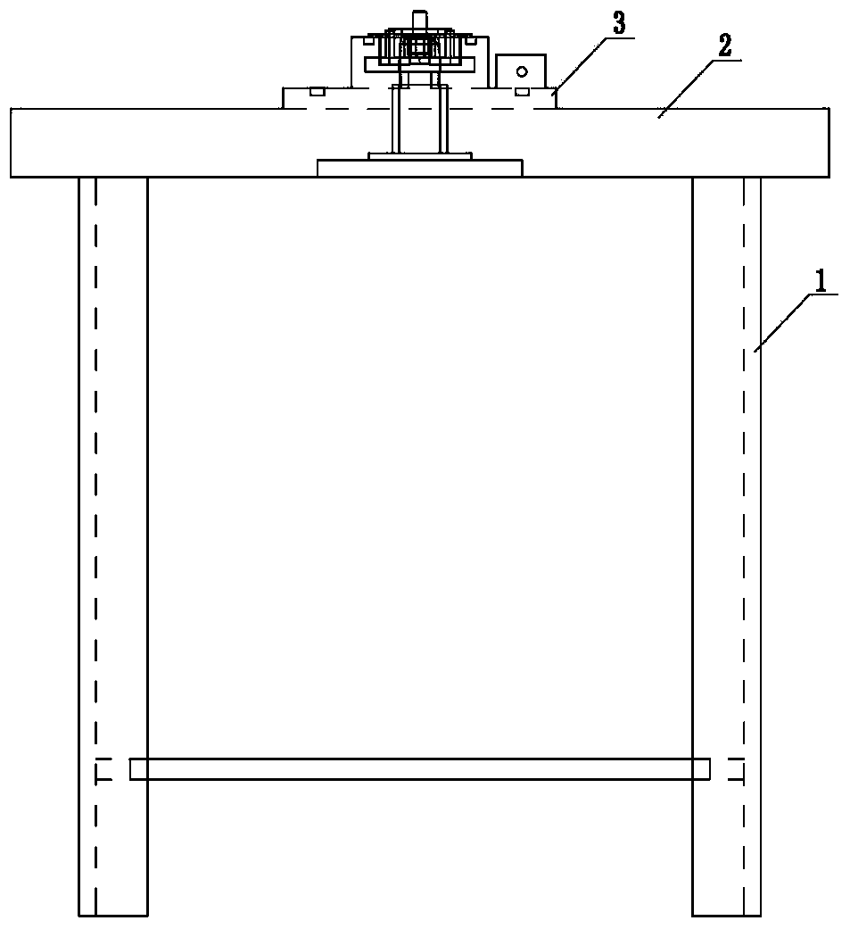
[0021] Such as Figure 1 to Figure 5 As shown, the technical scheme adopted by the present invention is as follows: a pneumatic clamping machine includes a bracket 1, a workbench 2, a mounting plate 3, a clamp spring seat 4, a pneumatic push spring assembly and a spring clip fixing assembly, wherein the above work The table 2 is fixedly arranged on the bracket 1; the above-mentioned installation plate 3 is fixed on the workbench 2, and the clamp spring seat 4 is fixed on the installation plate 3; the above-mentioned clamp spring seat 4 is provided with a groove body 5, and the groove body 5 is A triangular trough, one of its top corners is aligned with the outer surface of the clamp spring seat body 4, the top corner is provided with a discharge part 14, and the outer end surface of the discharge part 14 has a discharge port 15, the discharge port 15 It communicates with t...


PUM


Abstract

The invention discloses a pneumatic clamping springing machine which comprises a bracket, a workbench, a mounting plate, a clamping spring base, a pneumatic spring pushing component and a spring clamp fixing component, wherein the workbench is fixedly arranged on the bracket; the mounting plate is fixedly arranged on the workbench; the clamping spring base 4 is fixed on the mounting plate; a groove is arranged in the clamping spring base; the groove is arranged as a triangular groove; a vertex angle is aligned with the outer side face of the clamping spring base; a discharging part is arranged at the vertex angle; a discharging port is arranged on the outer end face of the discharging part; the discharging port is communicated with the groove; a through hole is arranged in the inner side wall of the groove; the pneumatic spring pushing component is arranged on the inner side of the through hole; the pneumatic spring pushing component is used for outward pushing a spring to the discharging part through the through hole; the spring is pushed out from the discharging port; the spring clamp fixing component is arranged on the outer side of the discharging part; a spring clamp is fixed by the spring clamp fixing component. The pneumatic clamping springing machine has a simple structure, convenience and quickness in operation, high production efficiency, high quality of products and high production safety.

Description

technical field [0001] The invention relates to a spring loading device, in particular to a pneumatic clamping machine. Background technique [0002] The torsion spring is one of the more complicated design principles among all spring categories. The coils of the torsion spring are either tightly wound or separately wound, and can withstand torsional loads (at right angles to the spring axis). The end of the spring can be wound into a hook or a straight torsion arm. The spring clip is a tool that is widely used in daily production and life. The spring clip consists of two clip bodies. The two clip bodies are connected by a torsion spring. The middle part of the torsion spring is spirally bent to form a cylinder. Straight line, extending outward respectively, the two ends of the torsion spring are respectively stuck on the two clip bodies of the spring clip, and the ends of the two clip bodies are pressed when in use, thereby compressing the torsion spring, so that the head ...

Claims


Application Information

Patent Timeline
IPC IPC(8): B23P19/00
CPCB23P19/00
Inventor 俞征
Owner 永春县产品质量检验所福建省香产品质量检验中心国家燃香类产品质量监督检验中心福建
Learn More