Hand rope release mechanism and hand rope release method

A handle and adjustment mechanism technology, which is applied in the direction of container manufacturing machinery, paper/cardboard containers, box production operations, etc., can solve the problems of poor accuracy of the end of the handle rope, large distance error of the handle rope, and large error of the length of the handle rope and other problems, to achieve the effect of high production efficiency, good automation and easy replacement

Inactive Publication Date: 2017-03-29
杭州汇八科技有限公司
View PDF8 Cites 0 Cited by
  • Summary
  • Abstract
  • Description
  • Claims
  • Application Information

AI Technical Summary

Problems solved by technology

[0006] The invention provides a handle rope release mechanism and a handle release method for placing the handle rope between two layers of handle paper, which solves the problems of low efficiency and low efficiency of manually placing the handle rope in the handle production process. The length error of the handle rope is large, the distance error between the two ends of the handle rope on the handle is large, and the position accuracy of the end of the handle rope on the handle paper is poor

Method used


Image

  • Hand rope release mechanism and hand rope release method
  • Hand rope release mechanism and hand rope release method
  • Hand rope release mechanism and hand rope release method

Examples


Embodiment 1

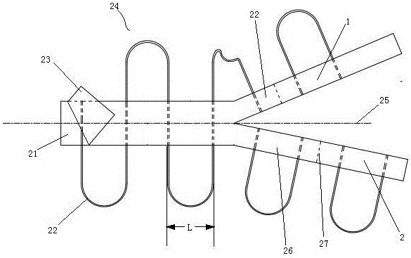
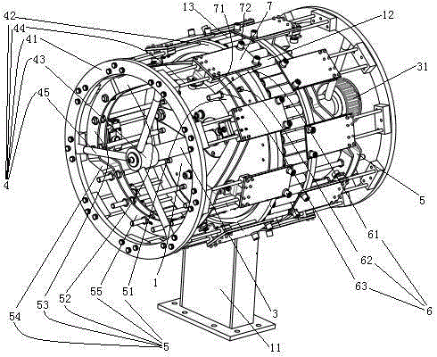
[0025] Embodiment one, see figure 1 , a handle rope release mechanism, characterized in that it includes a seat 1. The seat 1 is disc-shaped. The seat is designed to be disc-shaped, and any part of the peripheral surface of the seat can be used as a support surface for the handle rope, so that the positioning guide groove and the butt joint with the fitting structure are convenient. The seat 1 is provided with supporting feet 11 . A portion of the peripheral surface of the seat 1 constitutes a handle cord supporting surface 13 . Several drag-reducing rollers 12 are arranged on the peripheral surface of the seat 1 , and the drag-reducing rollers 12 are distributed along the circumferential direction of the seat 1 . The drag reducing roller 12 extends along the axial direction of the seat 1 .

[0026]A rotating shaft 3 is rotatably connected to the fixed seat 1 . The rotating shaft 3 runs through the fixed seat 1 and is coaxial with the fixed seat 1 . A transmission wheel ...

Embodiment 2

[0033] Embodiment 2, the difference from Embodiment 1 is that the guide groove is not provided with the hook head detachment guide section and the hook rope plate avoidance section, and an inlet is provided at the entrance end of the hook rope preparation section, so that the slider can be accurately Enter the hook rope preparation section.


PUM


Abstract

The invention relates to a handle rope reeling-off mechanism and method. The handle rope reeling-off mechanism comprises a fixed base, a pair of movable bases and a pair of guide grooves. The fixed base is provided with a handle rope supporting face which is a cylindrical face, and the movable bases and the handle rope supporting face are coaxial. The movable bases and the guide grooves are distributed on the two sides of a supporting base in the axial direction of the handle rope supporting face respectively; a plurality of sliding blocks which are evenly distributed in the circumferential direction of the handle rope supporting face, provided with hook heads and matched with the guide grooves are arranged on each movable base and are connected to rope hooking plates on the movable bases in a sliding mode. The rope hooking plates on the movable bases are staggered at intervals; each guide groove comprises a rope hooking preparation segment, a rope hooking and pulling segment and a positioning segment which are sequentially arranged in the circumferential direction of the handle rope supporting face. According to the mechanism, in the production process of a handle, the problems that a handle rope is manually placed, the efficiency is low, the length error of the handle rope is large, the distance error between the two ends of the handle rope on the handle is large, and the accuracy of the end of the handle rope on handle paper is poor can be solved.

Description

technical field [0001] The invention relates to a device and a method for processing a handle on a portable paper bag, in particular to a handle-releasing mechanism and a handle-releasing method, which belong to the field of paper bag processing. Background technique [0002] There are two kinds of structures for the user to carry the existing hand-held paper bag, one is the hand-held hole directly opened on the bag body, and the other is to be connected to the bag body to carry the hand rope. [0003] There are two ways to fix the hand strap. One is to directly fix the two ends of the hand rope on the bag body. In Chinese Patent No. 2004200254298, the date of authorization announcement is March 2, 2005, and the patent literature titled "Paper Bag" discloses a paper bag in which the hand rope is directly fixed on the bag body. The other is to paste the two ends of the handle rope between two layers of handle paper, and then realize the fixing of the handle rope by pasting ...

Claims


Application Information

Patent Timeline
Patent Type & Authority Patents(China)
IPC IPC(8): B31B50/86
Inventor 李璟
Owner 杭州汇八科技有限公司
Why Eureka
Try Eureka