Eureka AIR delivers breakthrough ideas for toughest innovation challenges, trusted by R&D personnel around the world.

Railway-vehicle air-conditioner air supplying and returning system

A rail vehicle and wind system technology, which is applied in the field of rail vehicle air-conditioning return air system, can solve problems such as uneven distribution, slow flow of air tissue in local areas, and the impact of air quality and comfort in the car, so as to achieve uniform distribution and improve air quality. In-vehicle air flow organization and the effect of optimizing the air environment in the car

Active Publication Date: 2014-12-24
CRRC NANJING PUZHEN CO LTD
View PDF7 Cites 10 Cited by
  • Summary
  • Abstract
  • Description
  • Claims
  • Application Information

AI Technical Summary

Problems solved by technology

Due to the difference in the position of each air supply port relative to the air return port in this way of supplying and returning air, the air tissue flow in the local area is slow, and the temperature field, humidity field and velocity field in the car are unevenly distributed, thus affecting the air quality and comfort in the car.

Method used


Image

  • Railway-vehicle air-conditioner air supplying and returning system
  • Railway-vehicle air-conditioner air supplying and returning system
  • Railway-vehicle air-conditioner air supplying and returning system

Examples


Embodiment Construction

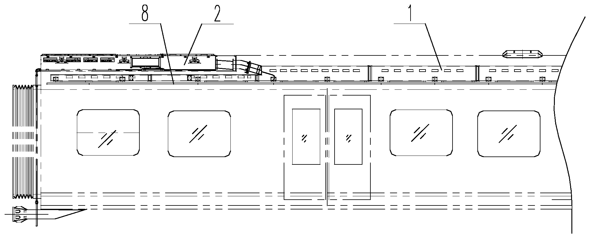
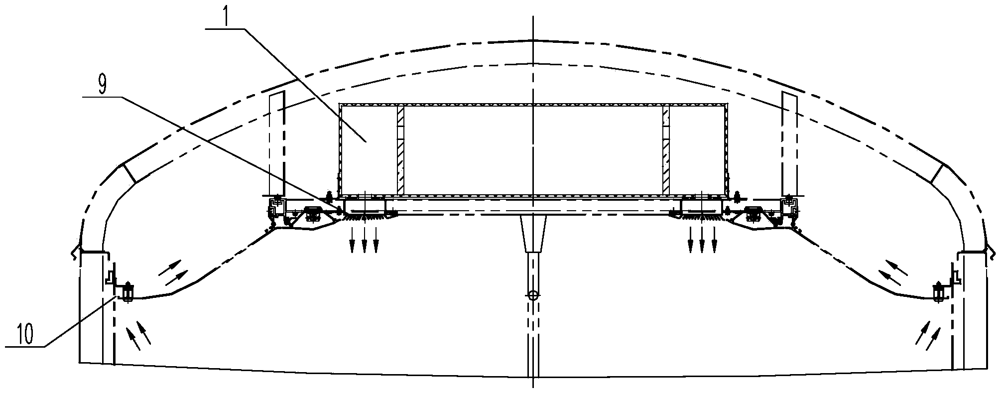
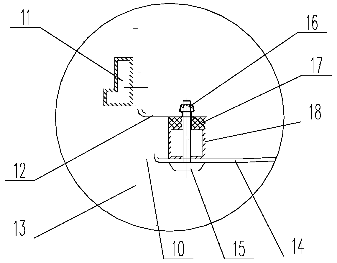
[0021] Such as Figure 1 to Figure 5 As shown, the rail vehicle air conditioner air return system in this embodiment includes air conditioners 2 ( figure 1 Only half of the car is drawn in the picture, and the structure of the other half is symmetrical to it), there is a through-type main air duct 1 above the flat roof of the passenger compartment, the air outlet of the air conditioner is connected to the main air duct 1, and the main air duct 1 passes through the delivery system below. The air outlet 9 supplies air to the passenger compartment; the air conditioner has a first return air outlet fixed on the flat roof of the vehicle end and a second return air outlet located above the flat roof of the vehicle end, and the lower edge of the side roof 14 of the passenger compartment is connected to the side wall frame 11 The connecting iron 12 is fixed, and a spacer 18 is arranged between the connecting iron 12 and the upper surface of the lower edge of the side top plate 14, and...


PUM


Abstract

The invention relates to a railway-vehicle air-conditioner air supplying and returning system, which comprises air conditioners, wherein the air conditioners are arranged at both ends of a vehicle top, a through-type main air channel is arranged above a guest-room flat-top plate, an air outlet of each air conditioner is connected with the main air channel, and air is supplied to a guest room by the main air channel through an air-supplying opening which is formed below the main air channel; each air conditioner is provided with a first air-returning opening which is fixed to a vehicle-end flat-top plate and a second air-returning opening which is positioned above the vehicle-end flat-top plate, the lower edge of a guest-room lateral top plate is fixed to a connecting iron which is arranged on a lateral-wall framework through bolts, a cushion block is arranged between the connecting iron and the upper surface of the lower edge of the lateral top plate, an air-returning channel is formed between the lateral top plate and a lateral wall, and the air-returning channel is communicated with the second air-returning opening. According to the railway-vehicle air-conditioner air supplying and returning system, two air-returning channels are respectively formed between the guest-room lateral top plate and the two lateral walls, and the air-returning openings are formed in a vehicle-end flat top. One part of circulating air in a vehicle enters the upper space of a vehicle top through the air-returning channels and flows back to a machine set, and the other part of the circulating air directly flows back to the machine set through the air-returning openings in the vehicle-end flat top. According to the scheme, the airflow organization in the vehicle is improved, and the uniformity of a temperature and humidity field and a velocity field is improved.

Description

technical field [0001] The invention relates to a rail vehicle air conditioner sending and returning air system, and belongs to the technical field of rail vehicle air conditioning. Background technique [0002] The air supply and return air system of the railway vehicle air conditioner is generally used in the traditional form to supply air from the top of the passenger compartment and return air to the flat top of the car end. Set distributed air supply outlets on the top of the passenger compartment, and centralized air return outlets on the flat top of the car end. The air is sent into the car through the upper air duct on the roof of the passenger compartment from the top air outlet. After mixing with the air in the car, most of the air flows to the end of the car and returns to the air conditioning unit through the air return port on the flat roof. A small part of the air passes through the waste exhaust. The device is ejected from the vehicle. Due to the difference ...

Claims


Application Information

Patent Timeline
Patent Type & Authority Applications(China)
IPC IPC(8): B61D27/00
Inventor 吴李丽于海飞杨智朋高健飞王卫
Owner CRRC NANJING PUZHEN CO LTD
Why Eureka
Eureka Blog
Learn More