Toolbox rotation direction position restriction structure

A technology of rotation direction and tool box, which is applied in the direction of spare tire arrangement, transportation and packaging, vehicle parts, etc., and can solve the problems of destroying the tool box, damaging the inner peripheral surface of the wheel part, and generating noise, etc.

Inactive Publication Date: 2016-05-18
SUZUKI MOTOR CORP
View PDF9 Cites 0 Cited by
  • Summary
  • Abstract
  • Description
  • Claims
  • Application Information

AI Technical Summary

Problems solved by technology

[0009] However, in the above-mentioned conventional tool box, in the tool box configured to only have recesses and holes for avoiding fastening members, in the state where it is housed in the wheel portion of the spare tire, the tool box may be affected by the vibration during the running of the vehicle. Therefore, it may cause the occurrence and situation: Noise is generated due to contact between the tool box and the wheel part of the spare tire, and other surrounding parts, and it is damaged
[0010] In addition, in the tool box configured to be provided with protrusions and fitting parts that can be fitted with the holes of the spare tire to prevent rotational movement, factory assembly workers or general users actually put the tool box into the spare tire from above. Since the hole on the side of the spare tire is provided at any position in the wheel part of the vehicle, the position of the protrusion on the side of the tool box, the position of the fitting part, and the position of the hole on the side of the spare tire cannot be visually confirmed. Install the tool box while confirming the fitting state between the tool box and the spare wheel
Therefore, it not only takes a lot of time to accommodate the tool box in the wheel part, but also, in the worst case, the tool box may be damaged during the assembly work, and the inner peripheral surface of the wheel part of the spare tire may be damaged.
Moreover, when the vehicle is running in a state where the tool box and the spare tire are not fitted in the desired predetermined position, the tool box and the wheel portion of the spare tire and Friction noise, damage, and paint peeling due to friction between other surrounding parts

Method used


Image

  • Toolbox rotation direction position restriction structure
  • Toolbox rotation direction position restriction structure
  • Toolbox rotation direction position restriction structure

Examples


Embodiment Construction

[0031] Hereinafter, the present invention will be described in detail based on embodiments of the drawings.

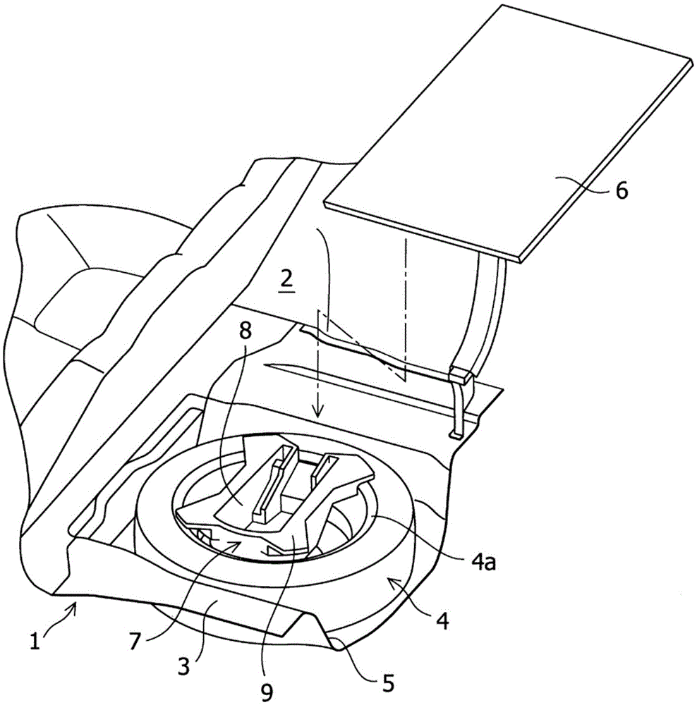
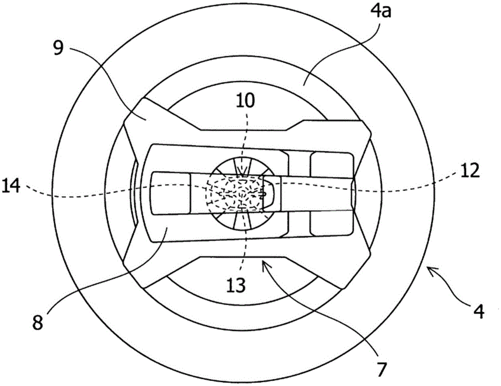
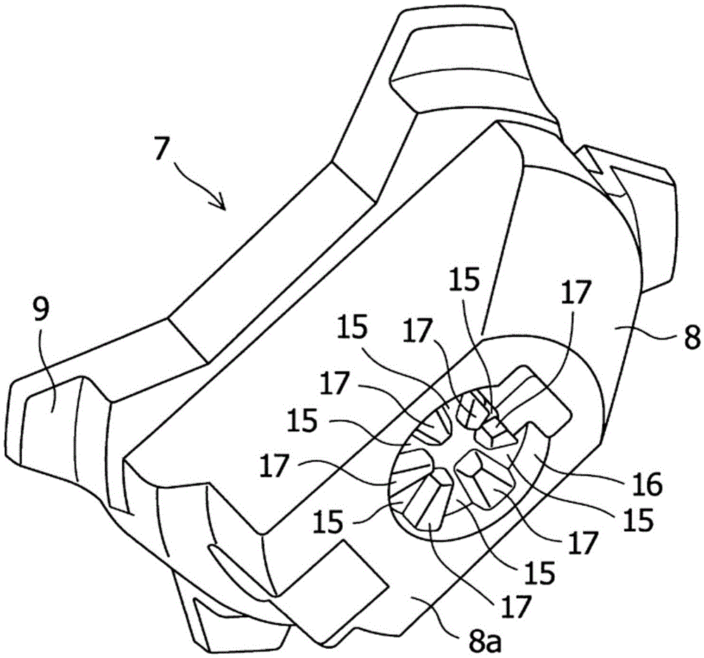
[0032] Figure 1 to Figure 7 It is a figure which shows the rotation direction position control structure of the toolbox which concerns on embodiment of this invention.

[0033] Such as figure 1 As shown, in the rear part 1 of the vehicle to which the rotation direction position limiting structure of the toolbox according to the embodiment of the present invention is applied, a trunk 2 for loading luggage is provided, and the floor 3 of the trunk 2 is formed in a downwardly concave manner. In the storage recess 5 for storing the spare tire 4 . In addition, a flat luggage board 6 constituting the floor surface is provided on the floor 3 in the luggage room 2 , and the upper opening of the storage recess 5 is covered with the luggage board 6 .

[0034] The spare tire 4 is installed inside the storage recess 5 in a state of lying down, and the wheel portion 4 a is fas...


PUM


Abstract

PROBLEM TO BE SOLVED: To provide a structure for the regulation of a rotation position of a tool box in which it is not required for separately providing a presser structure of the tool box, the tool box received in a wheel part of a spare tire can be prevented from rotationally moving due to vibration during travel of a vehicle, and an allophone can be prevented from being generated due to contact thereof with the wheel part of the spare tire or other peripheral parts.SOLUTION: This invention provides a structure in which a wheel part 4a of a spare tire 4 is fixed to a vehicle body side by a fastening member, a tool box 7 is received in the wheel part 4a and a position of the received tool box 7 in a rotation direction is regulated. In the structure, a head 12 of the fastening member 10 is provided with a holding part 14 which can hold the fastening member 10, the holding part 14 includes a flat plate part 14a having a flat surface along a direction orthogonal to a central axis of the fastening member 10 in a rotation direction when fastening thereof, and a bottom surface 8a of a box body 8a of the tool box 7 is provided with a groove part 15 fitting to the flat plate part 14a.

Description

technical field [0001] The present invention relates to a rotation direction position limiting structure of a tool box accommodated in a wheel portion of a spare tire fixed to a trunk or the like at the rear of a vehicle. Background technique [0002] Conventionally, a trunk for loading luggage is provided at the rear of the vehicle, and a recess for accommodating a spare tire is formed under the floor of the trunk. In addition, a flat luggage board constituting a floor surface is provided in the luggage compartment, and the upper opening of the recess is covered with the luggage board. [0003] The wheel portion of the spare tire is fixed to the vehicle body side by a fastening member (spare tire holder), and a tool box for storing tools and small items is accommodated in the wheel portion. The tool box is a storage container made of resin injection molding, resin blow molding, or synthetic resin foam, and is used to fix tools and the like placed in the wheel portion of th...

Claims


Application Information

Patent Timeline
Patent Type & Authority Patents(China)
IPC IPC(8): B62D43/10B60R11/06
CPCB60R11/06B62D43/10
Inventor 黑川启二阿莫瑞什·高拉夫
Owner SUZUKI MOTOR CORP
Why Eureka
Try Eureka