Lifting device with quick locking

A kind of equipment and fast technology, applied in the direction of textiles and papermaking, paper machines, press parts, etc., can solve the problems of difficult control, increased difficulty, and impact of the adjustment process, and achieve the effect of simple reinstallation design and reduced investment costs

Active Publication Date: 2017-04-12
VALMET TECH OY
View PDF6 Cites 0 Cited by
  • Summary
  • Abstract
  • Description
  • Claims
  • Application Information

AI Technical Summary

Problems solved by technology

As a whole, the device is rather complex, and making one adjustment affects two other adjustments, so the entire adjustment process is difficult to control
In addition, the implementation of the mutual fixation of the shoe roll and the support arm to the structure further increases the complexity of the adjustment, thereby increasing the difficulty of aligning the bearing housings of the shoe roll and the counter roll

Method used


Image

  • Lifting device with quick locking
  • Lifting device with quick locking
  • Lifting device with quick locking

Examples


Embodiment Construction

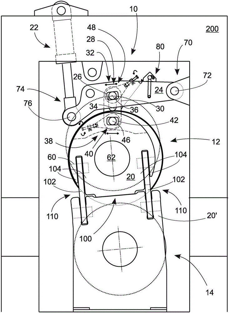
[0023] figure 1 A general view showing the connection between the shoe roll 12 and its counter roll 14 under the locked locking device 110 . In the locked position, the bearing housing 20 of the shoe roll 12 and the bearing housing 20' of the counter roll 14 overlap with the contact surface 100, which is an addition to the bearing housings 20 and 20' of the locking device 110 104 also coincides with the connecting arm 102 between the two additional parts 104 . In order to be able to remove the band jacket of the shoe roller 12 from the roller for replacement, the locking device 110 must be released and the shoe roller 12 must be lifted into the air. Strip sheath 16 in figure 2 shown in . Returning the shoe roller 12 to its position on the counterroll 14 with the lifting device according to the invention is not practically possible or at least extremely difficult and time-consuming to align the contact surface 100 with conventional lifting tools.

[0024] figure 1 A lifti...


PUM


Abstract

The invention relates to a quick-locking lifting device for supporting or installing a bearing housing of a paper machine roller or a board machine roller at a selected angle onto a mating element, and the roller (12) here is composed of a roller, e.g., a shoe roller, provided with a belt-shaped protective jacket. The lifting device (10) comprises a fulcrum (18) on the bearing housing (20); a lifting arm (24) operated by a lifting means (22), and an elongated hole (26) forming a support point (28) on the lifting arm; at least one support arm (30), which connects the support point of the lifting arm with the fulcrum of the bearing housing; a deflection means (38) enabling the fulcrum in the bearing housing to be dislocated in a lateral direction; and also a bolt connecting means (40) on the fulcrum of the bearing housing, the bolt connecting means comprising at least one elongated hole in the bearing housing, an opening (44) in the support arm and a bolt (46) connecting the elongated hole with the opening, wherein the deflection means is connected with the bolt connecting means.

Description

technical field [0001] The invention relates to a quick-lockable lifting device for supporting a bearing housing of a paper or board machine roll for mounting the roll on a counter element at a selected angle, wherein the roll is provided with Consisting of rollers (such as shoe rollers) with a belt-shaped sheath, the lifting device includes: a fulcrum on the bearing housing; a lifting arm manipulated by the lifting device, on which a long hole (such as a narrow hole); at least one support arm, which connects the support point of the lifting arm and the fulcrum of the bearing housing to each other; and a deflection device for displacing the fulcrum of the bearing housing in the lateral direction. Background technique [0002] During the production of fibrous material webs, at least one roll provided with a belt-shaped sheath, such as a shoe roll, is usually provided. During maintenance of the roll, in order to replace the belt-shaped sheath, the belt-shaped The end faces ar...

Claims


Application Information

Patent Timeline
Patent Type & Authority Patents(China)
IPC IPC(8): D21G9/00
CPCD21F3/02D21G1/002
Inventor 尤哈·温帕里维莱·埃罗宁
Owner VALMET TECH OY
Why Eureka
Try Eureka