
Throttling-governing butterfly valve

A throttling adjustment and butterfly valve technology, which is applied in the direction of lifting valves, valve devices, sliding valves, etc., can solve the problems of slightly opening butterfly valves, the inability to accurately adjust the flow rate, and the inability to fine-tune the flow rate of butterfly valves, etc., to achieve accurate flow adjustment and overall structure Simple, easy-to-use effect

Active Publication Date: 2014-12-24
SHANGHAI HUGONG VALVE FACTORY (GRP) CO LTD
View PDF8 Cites 9 Cited by
  • Summary
  • Abstract
  • Description
  • Claims
  • Application Information

AI Technical Summary

Problems solved by technology

In the prior art, people can only adjust the flow of the butterfly valve by changing the opening angle of the butterfly plate, but when the butterfly plate is at a fixed opening angle, people cannot fine-tune the flow of the butterfly valve, and when the butterfly plate When it is in the closed state, people cannot slightly open the butterfly valve without opening the butterfly plate, so that the butterfly valve cannot adjust the flow more accurately when the butterfly plate is at a fixed opening angle, and the butterfly valve cannot be realized when the butterfly plate is closed. The micro-opening operation

Method used


Image

  • Throttling-governing butterfly valve
  • Throttling-governing butterfly valve
  • Throttling-governing butterfly valve

Examples


Embodiment Construction

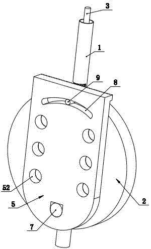
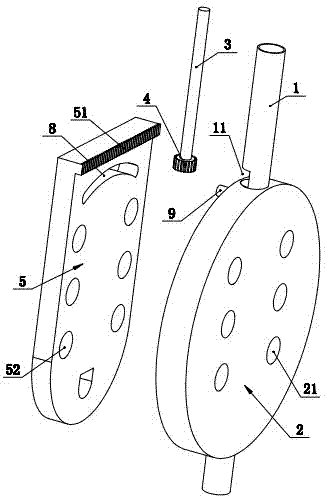
[0014] Such as figure 1 , 2 , 3, 4, and 5 show a throttling regulating butterfly valve, including a valve stem 1, a butterfly plate 2, a gear shaft 3, a gear 4 and a throttle plate 5, and the butterfly plate 2 is mounted on the valve stem 1 On the lower end, the gear shaft 3 is installed in the valve stem 1, and an axial limit is formed between the upper end of the gear shaft 3 and the upper port of the valve stem 1, and the upper end of the gear shaft 3 is clamped with a Axial limiting sleeve 6, said axial limiting sleeve 6 is fixedly mounted on the upper port of valve stem 1 through locking screw 61, and a seal is also provided between said axial limiting sleeve 6 and gear shaft 3 Packing 62, of course, the upper end of the gear shaft 3 and the upper port of the valve stem 1 can also be fixed in an axial position through other connection structures, the gear 4 is fixed on the lower end of the gear shaft 3, and The valve stem 1 is correspondingly provided with a notch 11 fo...


PUM


Abstract

The invention discloses a throttling-governing butterfly valve. The throttling-governing butterfly valve comprises a valve rod, a butterfly plate, a gear shaft, a gear and a throttle plate, wherein the gear is fixedly mounted at the end part of the lower end of the gear shaft, a gap which is used for exposing a part of the gear is correspondingly formed in the valve rod, a tooth face which forms engaged linkage with the exposed part of the gear is correspondingly formed at the upper end of the throttle plate, the lower end of the throttle plate is hinged to the lower end of the butterfly plate, the hinged turning of the throttle plate on the butterfly plate can be formed through the matched turning between an upper tooth face of the throttle plate and the gear, a plurality of flow guiding holes are uniformly formed in the butterfly plate, a throttling hole, which has the same hole diameter as that of each flow guiding hole, is formed in the throttle plate corresponding to the location of each flow guiding hole, and the throttling holes and the flow guiding holes can form mutual misalignment or alignment due to the hinged turning of the throttle plate and the butterfly plate. Through the structural arrangement, the butterfly valve can more accurately adjust flow when the butterfly plate is in a fixed opening angle, and the butterfly valve can be slightly opened when the butterfly plate is in a closed state.

Description

technical field [0001] The invention relates to a valve, in particular to a butterfly valve capable of throttling adjustment. Background technique [0002] Butterfly valve is a commonly used valve. Its structure usually includes a valve body, a valve stem and a butterfly plate. The butterfly plate is installed in the valve body. The lower end of the valve stem penetrates into the valve body and is fixed with the butterfly plate. The rod can drive the butterfly plate to rotate, thereby realizing the normal opening and closing of the butterfly valve. In the prior art, people can only adjust the flow of the butterfly valve by changing the opening angle of the butterfly plate, but when the butterfly plate is at a fixed opening angle, people cannot fine-tune the flow of the butterfly valve, and when the butterfly plate When it is in the closed state, people cannot slightly open the butterfly valve without opening the butterfly plate, so that the butterfly valve cannot adjust the...

Claims


Application Information

Patent Timeline
Patent Type & Authority Applications(China)
IPC IPC(8): F16K1/22F16K1/36F16K1/32
CPCF16K1/223F16K1/36F16K3/085
Inventor 黄建斌
Owner SHANGHAI HUGONG VALVE FACTORY (GRP) CO LTD
Learn More