LED (Light Emitting Diode) street lamp

A technology of LED street lamps and lamp bodies, which is applied to the loss prevention measures of lighting devices, cooling/heating devices of lighting devices, outdoor lighting, etc., can solve the problems of poor heat dissipation effect, affecting the service life of LED street lamps, and poor heat dissipation effect, etc.

Inactive Publication Date: 2014-12-24
王向东
View PDF4 Cites 1 Cited by
  • Summary
  • Abstract
  • Description
  • Claims
  • Application Information

AI Technical Summary

Problems solved by technology

But generally speaking, street lamps are located outdoors, affected by dust, ambient temperature and other factors, making heat dissipation an important factor affecting the life of LED street lamps
As we all know, there are three main ways of heat transmission: conduction, radiation, and convection. However, most of the existing LED street lights are snake head lights, and the heat dissipation method is mainly radiation heat dissipation, and the heat dissipation effect is not good.
When used for a long time, due to the influence of dust and other external environments, the heat dissipation effect will become worse and worse, so that the heat generated by the LED work will continue to accumulate, and the high temperature will lead to a sharp decrease in its life.
[0004] At the same time, traditional street lamp shells are generally made of thermally conductive metal or plastic. Although thermally conductive metal has good thermal conductivity, the production process is cumbersome, the molding options are narrow, and the production cost is relatively high; while the use of plastic reduces production costs, but the finished product has poor heat dissipation performance. , indirectly affects the service life of LED street lamps

Method used


Image

  • LED (Light Emitting Diode) street lamp
  • LED (Light Emitting Diode) street lamp
  • LED (Light Emitting Diode) street lamp

Examples


Embodiment Construction

[0023] It should be understood that the specific embodiments described here are only used to explain the present invention, not to limit the present invention.

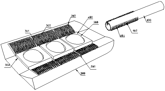
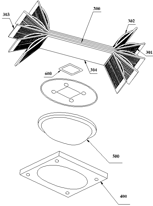
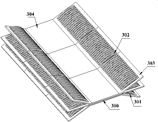
[0024] refer to Figure 1 to Figure 4 , an embodiment of an LED street lamp of the present invention is proposed, including a lamp post, a lamp post connecting rod 100, and a lamp body. The lamp post connecting rod 100 includes a built-in part embedded in the bottom of the lamp body and connected with the lamp body through screw connection, an external part exposed outside the lamp body and fixedly connected with the top of the lamp post, and evenly arranged on the side of the built-in part. A number of first strip-shaped incisions cut with a cutter, the first strip-shaped incision punches out a number of first heat dissipation holes 101 and arched first heat dissipation fins 102 through the punching machine; the lamp body includes a lamp housing 200, mounted on The radiator 300 on the lamp housing 200, the LED light...


PUM


Abstract

The invention discloses an LED (Light Emitting Diode) street lamp, which comprises a lamppost, a lamppost connecting rod and a lamp body, wherein the lamppost connecting rod comprises a built-in part embedded in the bottom of the lamp body, and a built-out part exposed to the lamp body, wherein a plurality of first strip-shaped cuts cut by a cutter are arranged on the side surface of the built-in part, and are punched by a punch into a plurality of first radiating holes and arched first radiating fins, and the lamp body comprises a lamp shell, a radiator, LED light source structures, light transmitting covers and fasteners; the lamp shell is made by glass fiber reinforced javascript:void(0);or a PC (Poly Carbonate) material, and the radiator is formed by transversely arranging and splicing a plurality of radiating fins, or by longitudinally overlapping a plurality of radiating fins; the two ends of radiating bases of the radiating fins tilt out and extend out of radiating surfaces, and a plurality of second radiating holes and second radiating fins are arranged on the radiating surfaces. The LED street lamp provided by the invention has the advantages of simple structure, realization of ideal radiating effect by using a self-structure design, reduction in production cost due to the glass fiber reinforced javascript:void(0);or PC lamp shell, various shapes, long servie life and the like.

Description

technical field [0001] The invention relates to road lighting technology, in particular to an LED street lamp. Background technique [0002] In 1879, Shanghai's Ponte 16 Wharf lit up China's first light. Since then, with the advancement of technology, street lights have become an indispensable public facility in every city. With the continuous innovation of LED technology, LED will replace traditional light sources and become popular, so as to alleviate the increasingly severe energy crisis in the world and improve the living environment of human beings. [0003] LED street lamps are widely used in the field of road lighting due to their characteristics of energy saving, good chromaticity, maintenance-free and long life. But generally speaking, street lamps are located outdoors, and are affected by factors such as dust and ambient temperature, making heat dissipation an important factor affecting the life of LED street lamps. As we all know, there are three main ways of he...

Claims


Application Information

Patent Timeline
IPC IPC(8): F21S8/08F21V29/00F21V15/02F21V21/108F21W131/103F21Y101/02
Inventor 王向东
Owner 王向东
Why Eureka
Try Eureka