Valve negative pressure detecting system

A technology of negative pressure detection and valve, which is applied in the direction of measuring the rate of increase and deceleration of the fluid, using liquid/vacuum to measure the liquid tightness, etc., can solve the problems such as unfavorable detection of different valves, and achieve the effect suitable for industrial control

Inactive Publication Date: 2014-12-24
印波
View PDF0 Cites 3 Cited by
  • Summary
  • Abstract
  • Description
  • Claims
  • Application Information

AI Technical Summary

Problems solved by technology

The differential pressure detection method usually requires standard parts, which is not conducive to the detection of different valves

Method used


Image

  • Valve negative pressure detecting system

Examples


Embodiment 1

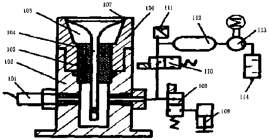
[0025] figure 1 It shows a schematic structural diagram of a valve negative pressure detection system according to an embodiment of the present invention. Such as figure 1 The shown valve negative pressure detection system includes a vacuum pressure sensor 101, a test base 102, a positioning guide block 103, a valve 104, a test cavity 105, and a mold 106. The vacuum pressure sensor 101 is connected to the test base 102, The test base 102 is provided with a mold 106, and the mold 106 is provided with a test cavity 105; one end of the valve 104 is located in the test cavity 105, and the other end penetrates the mold 106 and extends into the test base 102. The guide The positioning block 103 is located on the circumference of the middle of the valve 104.

[0026] A sealing end surface 107 is provided at one end of the valve 104 and the circumference of the inner wall of the test cavity 105.

[0027] The test base 102 is provided with a concave cavity, the mold 106 is provided with ...

Embodiment 2

[0036] This embodiment adopts the negative pressure detection method. When the valve is placed in the mold, the valve and the mold end face form a sealed end surface. At this time, the second test control valve is in the left position, and the test cavity forms a vacuum. After a few seconds, the second test control When the valve is in the right position after power failure, the vacuum pressure sensor starts to test the vacuum pressure in the test chamber, and returns the test value to the PLC for calculation and processing. When the next valve is placed on the test base, a new round of testing is started.


PUM


Abstract

The invention discloses a valve negative pressure detecting system. The valve negative pressure detecting system comprises a vacuum pressure sensor, a testing base, a positioning guide block, a valve, a testing cavity and a die. The vacuum pressure sensor is connected with the testing base, the die is arranged on the testing base, and the testing cavity is formed in the die. One end of the valve is located in the testing cavity, and the other end of the valve penetrates through the die and extends into the testing base. The positioning guide block is located on the circumference of the middle of the valve. According to the valve negative pressure detecting system, a detecting device only needs to be calibrated one time according to different detected valves, calibration can be stored in a PLC in the form of parameters so that the valve negative pressure detecting system can test the different valves conveniently, online control can be conveniently carried out in real time according to the different working conditions, and the valve negative pressure detecting system is especially suitable for industrial control.

Description

Technical field [0001] The invention relates to the technical field of air pressure detection, in particular to a valve negative pressure detection system. Background technique [0002] The sealing performance of the valve directly affects the engine's output power, fuel consumption and other important performance. At present, the commonly used airtightness detection methods mainly include wet and dry leak detection methods, while dry detection methods mainly include differential pressure detection methods. The wet detection method is relatively backward and is not conducive to industrial automation. The dry detection method usually uses air or nitrogen as the detection medium. The differential pressure detection method usually requires standard parts, which is not conducive to the detection of different valves. Summary of the invention [0003] The invention overcomes the shortcomings of the prior art and provides a valve negative pressure detection system that is easy to contr...

Claims


Application Information

Patent Timeline
Patent Type & Authority Applications(China)
IPC IPC(8): G01M3/26
Inventor 印波
Owner 印波
Why Eureka
Try Eureka