
Automatic diaphragm control method and system

An automatic iris and DC control technology, which is applied to components of TV systems, components of color TVs, TVs, etc., can solve the problems of decreased control accuracy, high input labor costs, and changes in the iris damping of the iris drive control circuit.

Inactive Publication Date: 2014-12-24
HUAWEI TECH CO LTD
View PDF2 Cites 23 Cited by
  • Summary
  • Abstract
  • Description
  • Claims
  • Application Information

AI Technical Summary

Problems solved by technology

[0004] However, the disadvantage of the existing automatic iris control method is that there are many types of lenses with automatic iris on the market, and parameters such as the DC driving voltage of the automatic iris lens of each model and brand, the coil damping coefficient of the iris, and the inertia coefficient of the iris blades has a difference
It is difficult to realize the automatic calibration of automatic aperture lenses of different models and brands with the methods of the prior art, and often requires human participation in the calibration of the aperture control parameters
As a result, the calibration of the automatic aperture takes a long time and requires a lot of labor costs
[0005] At the same time, since the aperture drive control circuit itself is easily affected by factors such as the external environment temperature, device characteristic differences, and aperture damping changes, the DC drive voltage of the aperture will undergo static offset and dynamic drift, which in turn will lead to manual calibration parameters set at the factory. Ineffective, making the control accuracy drop
However, the methods in the prior art cannot solve the problems of static offset and dynamic drift of the above-mentioned aperture drive control circuit

Method used


Image

  • Automatic diaphragm control method and system
  • Automatic diaphragm control method and system
  • Automatic diaphragm control method and system

Examples


Embodiment Construction

[0072] The technical solutions in the embodiments of the present invention will be clearly and completely described below in conjunction with the accompanying drawings in the embodiments of the present invention. Obviously, the described embodiments are only some, not all, embodiments of the present invention. Based on the embodiments of the present invention, all other embodiments obtained by persons of ordinary skill in the art without creative efforts fall within the protection scope of the present invention.

[0073] The invention provides a method and system for controlling the automatic aperture, which can realize automatic calibration of the automatic aperture lens, reduce time and labor costs; meanwhile, it can also solve the problems of static offset and dynamic drift of the DC control voltage of the aperture, and improve Aperture control precision.

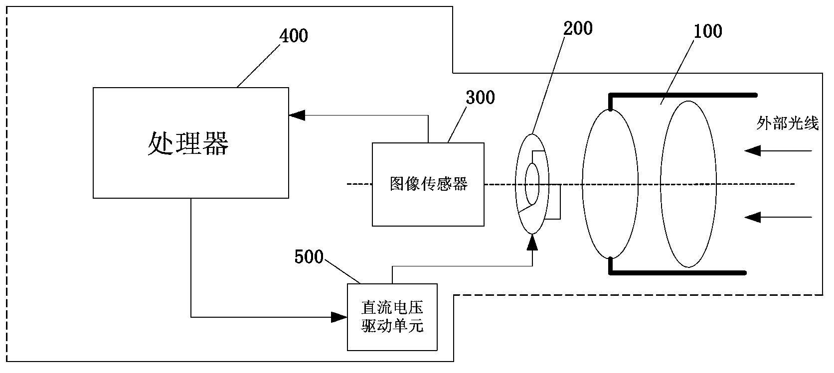
[0074] refer to figure 1 , is a typical application scene diagram of the automatic aperture control system described ...


PUM


Abstract

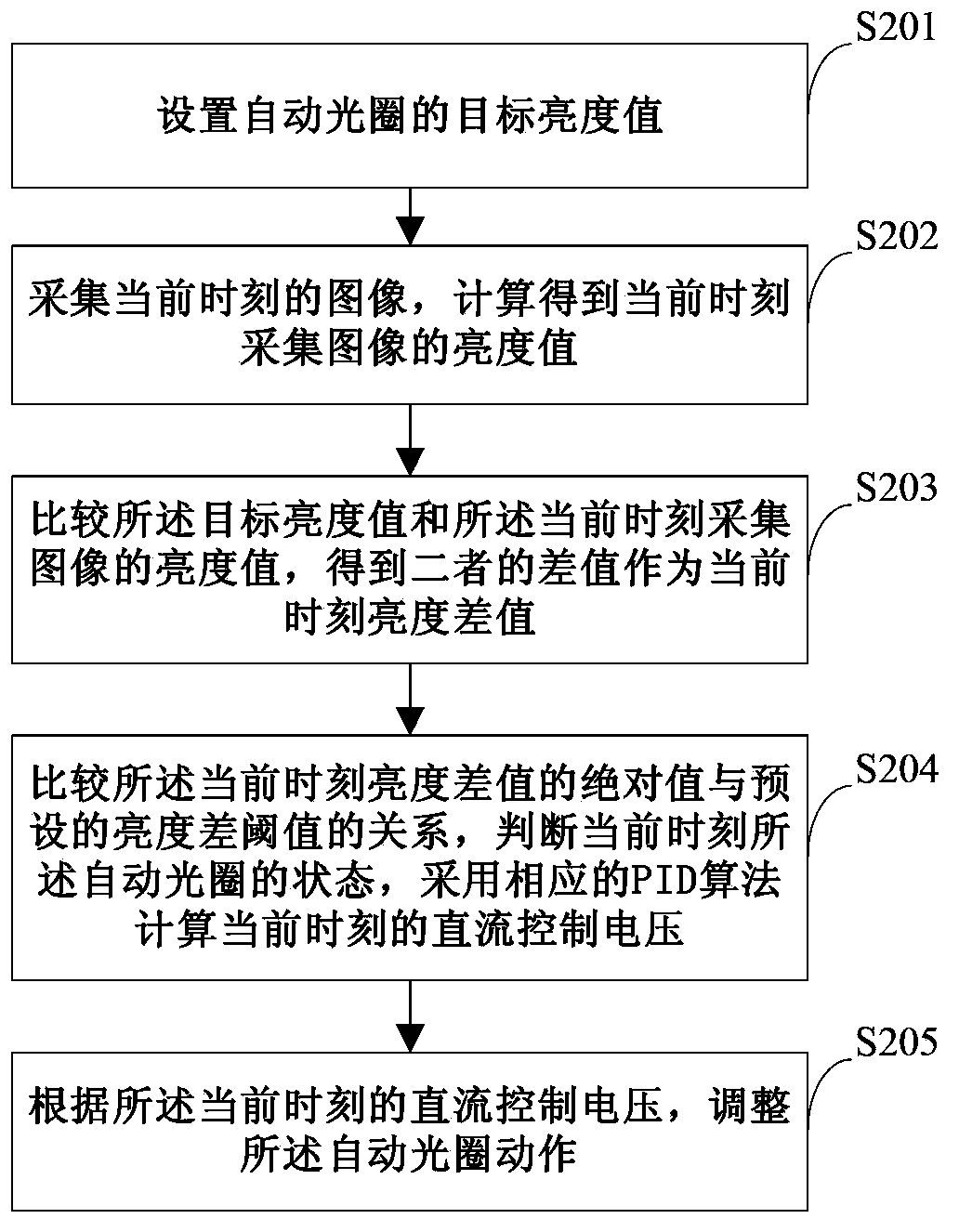
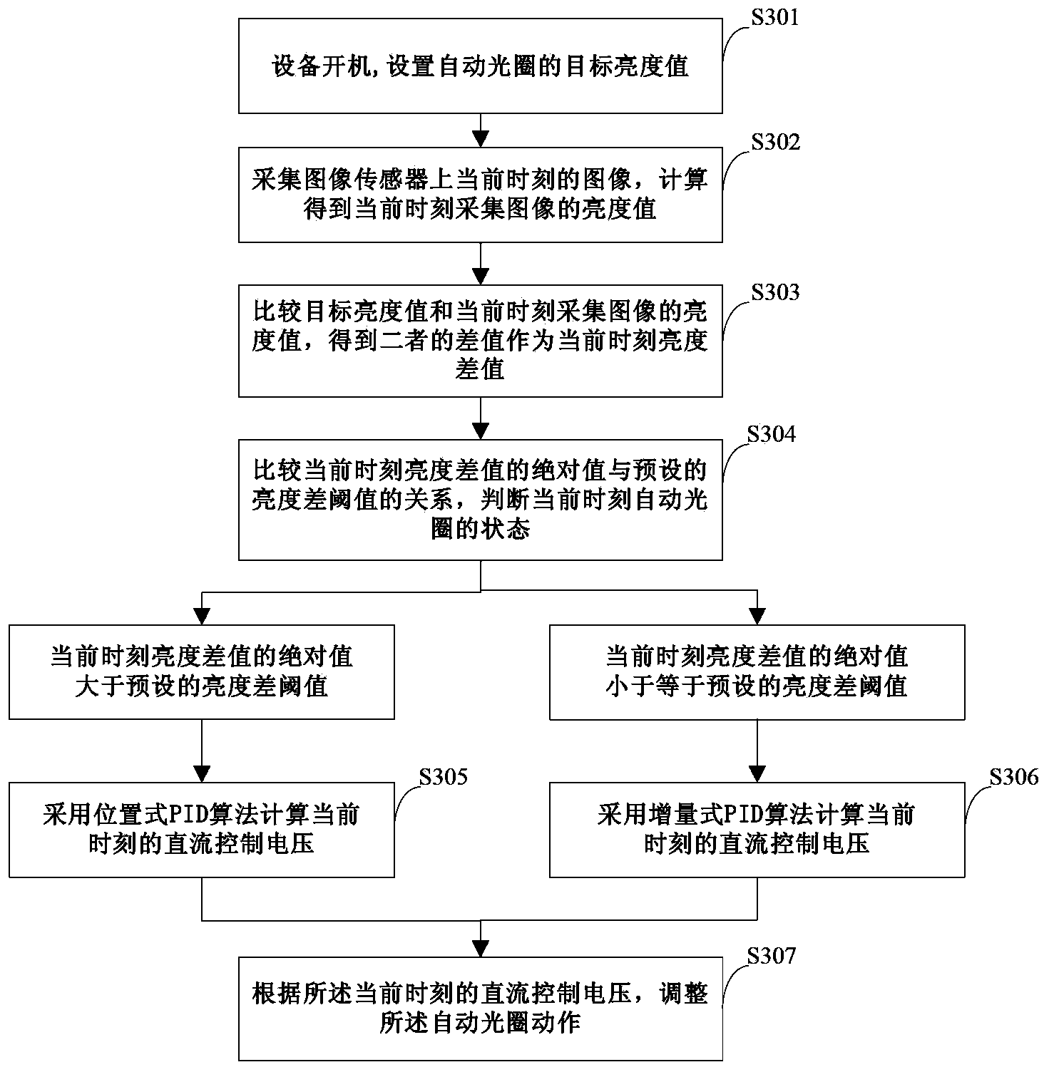
The embodiment of the invention discloses an automatic diaphragm control method. The automatic diaphragm control method comprises the steps of setting a target brightness value of an automatic diaphragm; acquiring an image at the current moment, and calculating a brightness value of the image acquired at the current moment; comparing the target brightness value with the brightness value of the image acquired at the current moment to obtain a difference value of the target brightness value and the brightness value of the image acquired at the current moment to serve as a brightness difference value at the current moment; comparing the relationship between an absolute value of the brightness difference value at the current moment and a preset brightness difference threshold value, judging the state of the automatic diaphragm at the current moment, and calculating direct current control voltage at the current moment by means of a corresponding PID algorithm; regulating the action of the automatic diaphragm according to the direct current control voltage obtained by calculation. The embodiment of the invention further discloses an automatic diaphragm control system. By means of the automatic diaphragm control method and system, an automatic diaphragm lens can be calibrated automatically, time is shortened, and labor cost is reduced. Meanwhile, the problems of static shift and dynamic deviation of a diagram driving control circuit can be solved, and the control accuracy of the diaphragm is improved.

Description

technical field [0001] The invention relates to the technical field of aperture control, in particular to an automatic aperture control method and system. Background technique [0002] The automatic iris of the camera lens is used to control the amount of incoming light by adjusting the size of the small holes between the iris blades in the lens, so as to achieve moderately exposed images under different lighting conditions. [0003] At present, the more commonly used automatic iris control method is mainly a DC driving method, which controls the opening and closing of the automatic iris by controlling the magnitude of the output DC driving voltage. Specifically, the existing DC driving method may include: presetting the initial driving voltage value, calculating the difference between the current brightness and the target brightness by collecting image Y / C component data, and calculating the required brightness according to the brightness difference. DC drive voltage to ad...

Claims


Application Information

Patent Timeline
IPC IPC(8): H04N5/235H04N5/232
CPCH04N17/002H04N23/75
Inventor 黄涛李健璋
Owner HUAWEI TECH CO LTD
Learn More