Actuator system for hydraulic clutch actuation

A technology for actuating systems and clutches, applied to clutches, fluid-driven clutches, non-mechanical-driven clutches, etc., can solve problems such as inability to ensure hydraulic fluid pressure or predetermined volume, and achieve accurate engagement or separation

Active Publication Date: 2014-12-24
SCHAEFFLER TECH AG & CO KG
View PDF6 Cites 8 Cited by
  • Summary
  • Abstract
  • Description
  • Claims
  • Application Information

AI Technical Summary

Problems solved by technology

However, the flow resistance is also dependent on the temperature of the fluid, so that after closing the connection opening it is not possible to ensure a predetermined pressure or a predetermined volume of hydraulic fluid in the actuation system

Method used


Image

  • Actuator system for hydraulic clutch actuation
  • Actuator system for hydraulic clutch actuation
  • Actuator system for hydraulic clutch actuation

Examples


Embodiment Construction

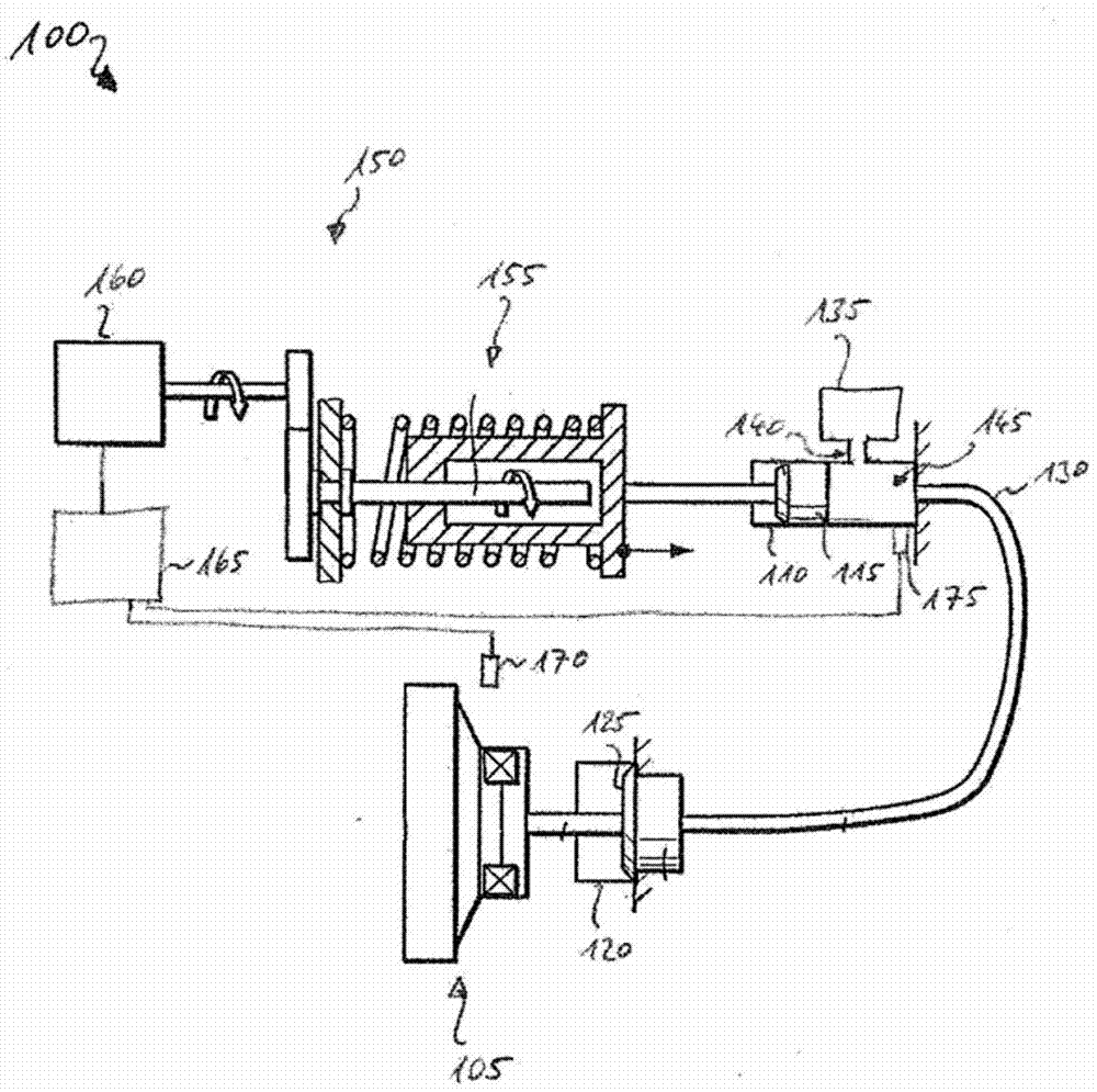
[0022] figure 1 An actuation system 100 for hydraulically actuating a clutch 105 is shown. The clutch 105 is provided for controlled closing or breaking of a force line in a drive train, in particular of a motor vehicle. In a preferred embodiment, a plurality of clutches 105 are provided in the drive train, of which at most one of the clutches is fully engaged at any one time.

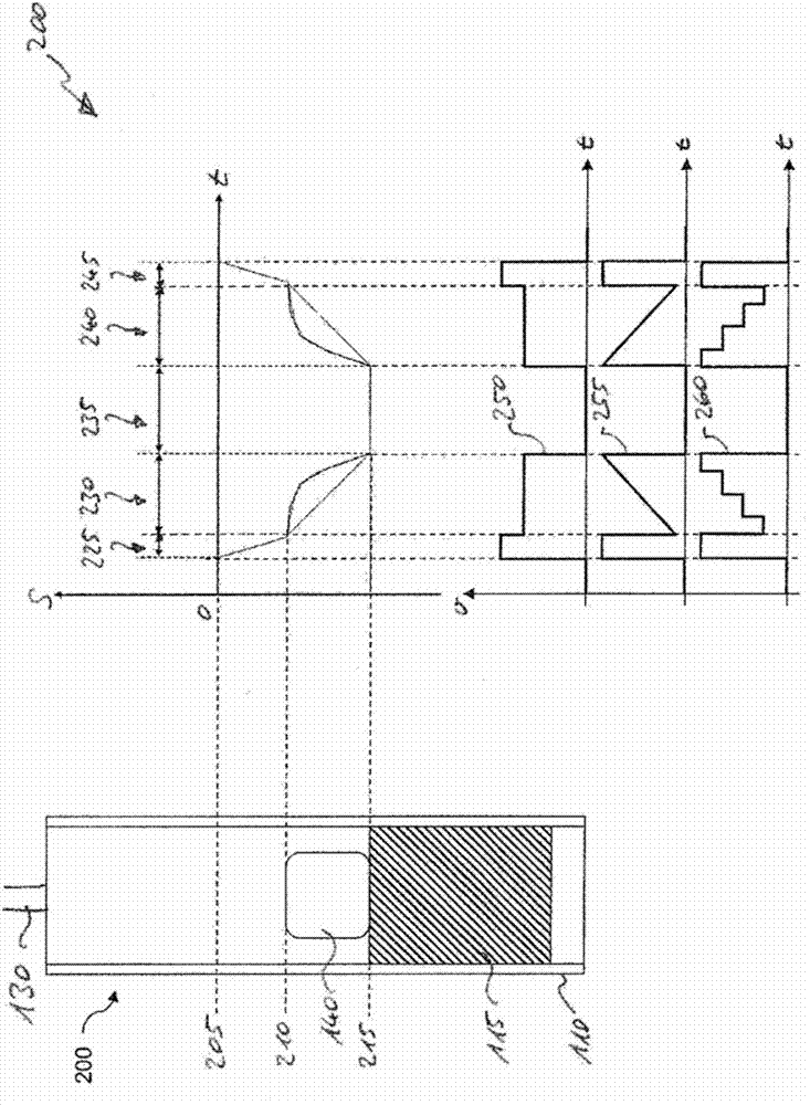
[0023] The actuation system 100 comprises: a master cylinder 110 in which a master piston 115 is housed; a slave cylinder 120 in which a slave piston 125 is housed; for fluidly connecting the cylinders 110 and 120 and a reservoir 135 which is fluidly connected to the master cylinder 110 in relation to the position of the master piston 115 by means of a connection opening 140 in the master cylinder 110 . Hydraulic fluid 145 is present in reservoir 135 , master cylinder 110 , pressure line 130 and slave cylinder 120 . The reservoir 135 is pressure-tightly closed relative to the surrounding environment...


PUM


Abstract

The invention relates to an actuator system for hydraulic actuation of a clutch, comprising a master cylinder having a master piston, a reservoir for receiving hydraulic fluid, a connection opening between the reservoir and the master cylinder, a degree of opening of the connection opening being dependent on a position of the master piston, and a hydrostatic actuator for controlling a position of the master piston. The actuator system according to the invention additionally has a control device for controlling the hydrostatic actuator so that a motion rate of the master piston is high when the connection opening is wide open, and low when the connection opening is only slightly open. In a method according to the invention, a position of the master piston is detected and the actuator is controlled depending on the position or degree of opening at different rates.

Description

technical field [0001] The invention relates to an actuation system for hydraulically actuating a clutch in a power train of a motor vehicle. In particular the invention relates to the control of hydrostatic actuators of the actuation system. Background technique [0002] Actuation systems for hydraulically actuating clutches include hydrostatic actuators, as are known, for example, from DE 10 2010 047 800 A1 or DE 10 2010 047 801 A1. Such an actuator operates a master piston in a master cylinder to exchange hydraulic fluid with a slave cylinder by means of a pressure line. The slave cylinder includes a slave piston that operates the clutch. [0003] In one specific embodiment, two clutches are provided in the drive train, which act on different drive shafts, only one of the clutches being engaged in each case. Here, it is common for the clutch to transmit force in the drive train if the pressure in the slave cylinder is sufficiently high. The opposite embodiment is know...

Claims


Application Information

Patent Timeline
IPC IPC(8): F16D29/00F16D48/06
CPCF16D29/005F16D48/064F16D2500/3026F15B7/08F15B7/10F16D25/14
Inventor 马尔科·特雷德莱因哈德·施特尔
Owner SCHAEFFLER TECH AG & CO KG
Why Eureka
Try Eureka