
Friction pad assembly for disc brakes

一种盘式制动器、摩擦垫的技术,应用在制动器的部件、制动器类型、带有受压制动面的制动器等方向,能够解决不能维持摩擦面积、不能确保制动特性等问题,达到减轻重量、成本降低、降低加工精度的效果

Inactive Publication Date: 2018-02-09
AKEBONO BRAKE IND CO LTD
View PDF8 Cites 0 Cited by
  • Summary
  • Abstract
  • Description
  • Claims
  • Application Information

AI Technical Summary

Problems solved by technology

[0003] In a disc brake device for a railway vehicle, since the disc rotor and the friction pad assembly are large in size, when the lining member to be pressed against the disc rotor is formed of an integral part, due to frictional heat, etc. Oscillation of the disc rotor, such an area of ​​the lining member that is not in contact with the disc rotor increases, so that a stable friction area cannot be maintained, and therefore, a stable braking characteristic cannot be ensured

Method used


Image

  • Friction pad assembly for disc brakes
  • Friction pad assembly for disc brakes
  • Friction pad assembly for disc brakes

Examples


Embodiment Construction

[0073] A description will be given specifically of a disc brake friction pad assembly according to an embodiment of the present invention with reference to the accompanying drawings.

[0074] Figure 1 to Figure 4 A disc brake friction pad assembly according to an embodiment of the invention is shown.

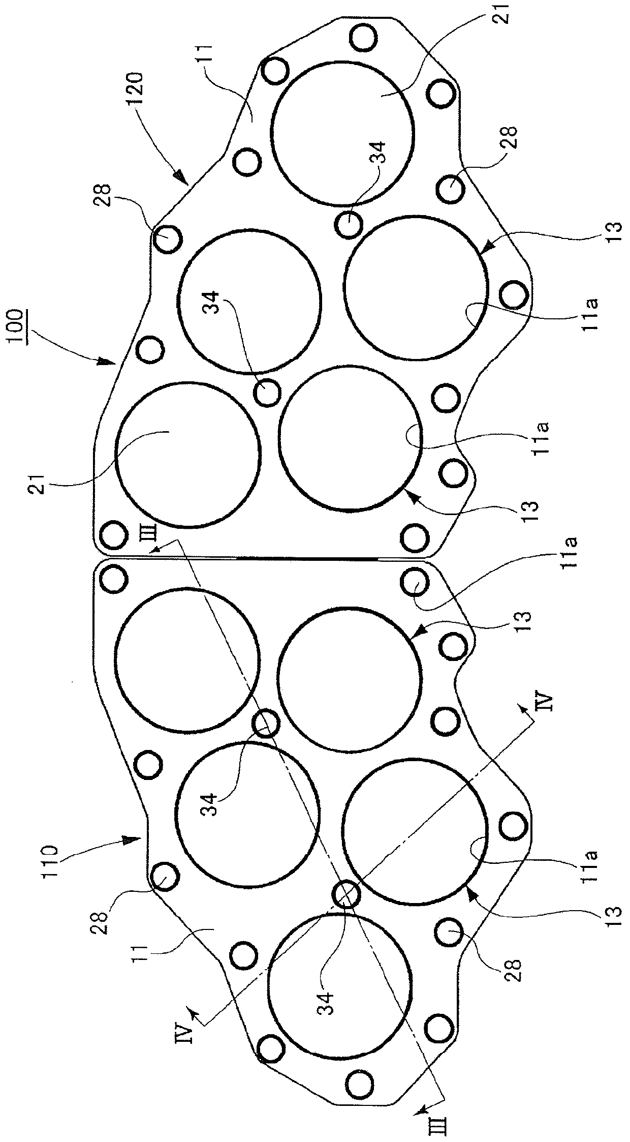
[0075] Such as figure 1 As shown, the disc brake friction pad assembly 100 according to this embodiment is used for a railway vehicle disc brake device, and consists of two-unit friction pads arranged side by side in the circumferential direction of a disc rotor (not shown) provided on a wheel shaft Components 110 and 120 make up.

[0076] The unit friction pad assemblies 110 and 120 are similarly constructed. They are respectively opposed to the disc rotor and can be driven by actuators placed in calipers (not shown) to advance and retreat relative to the disc rotor.

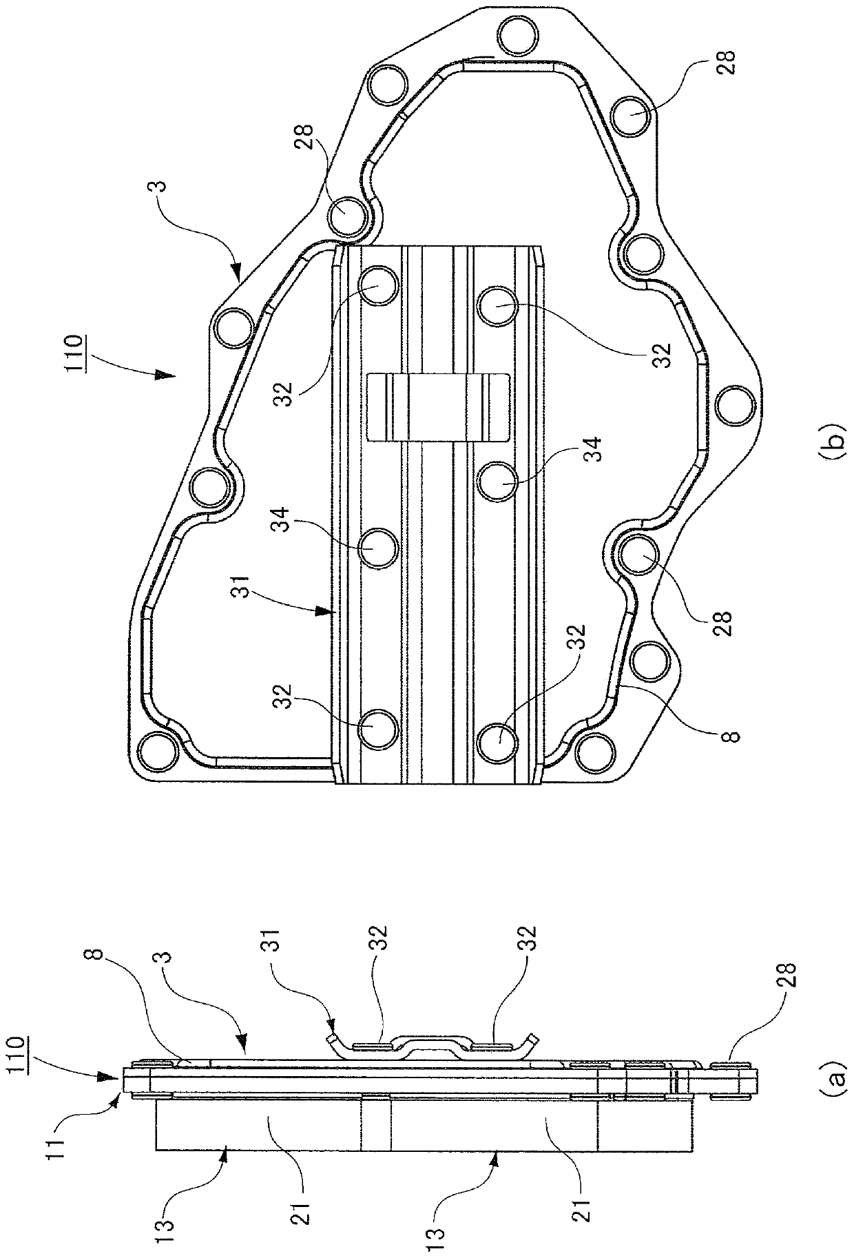
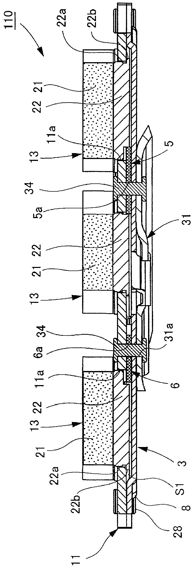
[0077] Such as figure 2 (a) to Figure 4 As shown, the friction pad assemblies 110 and 120 each includ...


PUM


Abstract

A unit friction pad assembly 110 constituting a disk brake friction pad assembly includes lining assemblies 13 which are oscillatably inserted into the guide hole portions 11a of a guide plate 11 to transmit a braking torque from plate engagement portions 22a to the guide plate 11 and are urged toward the guide plate 11 by spring members 24, and link plates 5, 6 for applying pressure from a torque receiving plate 3 to the multiple lining assemblies 13 and also for holding a clearance between the guide plate 11 and torque receiving plate 3.

Description

technical field [0001] The present invention relates to an improved disc brake friction pad assembly. Background technique [0002] The disc brake apparatus includes: a disc rotor fixed to a wheel shaft; a disc brake friction pad assembly consisting of a torque receiving plate arranged opposite to the disc rotor and a disc mounted to the torque receiving plate. a lining member of the rotor side surface; and a brake caliper to be fixed to the vehicle body frame and include therein an actuator for advancing and retreating the torque receiving plate relative to the disc rotor, whereby, The braking force is generated by sliding friction caused when the torque receiving plate is advanced toward the disc rotor to thereby press the lining member against the disc rotor. [0003] In a disc brake device for a railway vehicle, since the disc rotor and the friction pad assembly are large in size, when the lining member to be pressed against the disc rotor is formed of an integral part,...

Claims


Application Information

Patent Timeline
Patent Type & Authority Patents(China)
IPC IPC(8): F16D65/092B61H5/00
CPCB61H5/00F16D65/092F16D69/0408F16D65/0972F16D2069/0433
Inventor 吉川和宏
Owner AKEBONO BRAKE IND CO LTD
Features
  • Generate Ideas
  • Intellectual Property
  • Life Sciences
  • Materials
  • Tech Scout
  • Unparalleled Data Quality
  • Higher Quality Content
  • 60% Fewer Hallucinations
Learn More