
Electrolytic milling-grinding machining tool cathode with efficiency and precision and electrolytic milling-grinding method

A technology for machining tools and cathodes, applied in the field of electrolytic milling and grinding compound machining, can solve the problems of increased machining gap, unfavorable machining accuracy, reduced contact depth, etc., and achieves increased machining voltage, better machining flexibility, and increased penetration depth. Effect

Inactive Publication Date: 2018-08-17
NANJING UNIV OF AERONAUTICS & ASTRONAUTICS
View PDF6 Cites 19 Cited by
  • Summary
  • Abstract
  • Description
  • Claims
  • Application Information

AI Technical Summary

Problems solved by technology

However, in order to improve the efficiency of electrolytic milling and grinding, a larger machining voltage is often used. At this time, the current density in the machining gap increases, and the material removal speed increases. Although the feed speed of the tool cathode also increases, the distance between the tool cathode and the workpiece The machining gap tends to increase, and the contact depth between the abrasive grains and the workpiece gradually decreases, which is not conducive to the improvement of machining accuracy.

Method used


Image

  • Electrolytic milling-grinding machining tool cathode with efficiency and precision and electrolytic milling-grinding method
  • Electrolytic milling-grinding machining tool cathode with efficiency and precision and electrolytic milling-grinding method
  • Electrolytic milling-grinding machining tool cathode with efficiency and precision and electrolytic milling-grinding method

Examples


Embodiment Construction

[0029] The present invention will be further described below in conjunction with accompanying drawing:

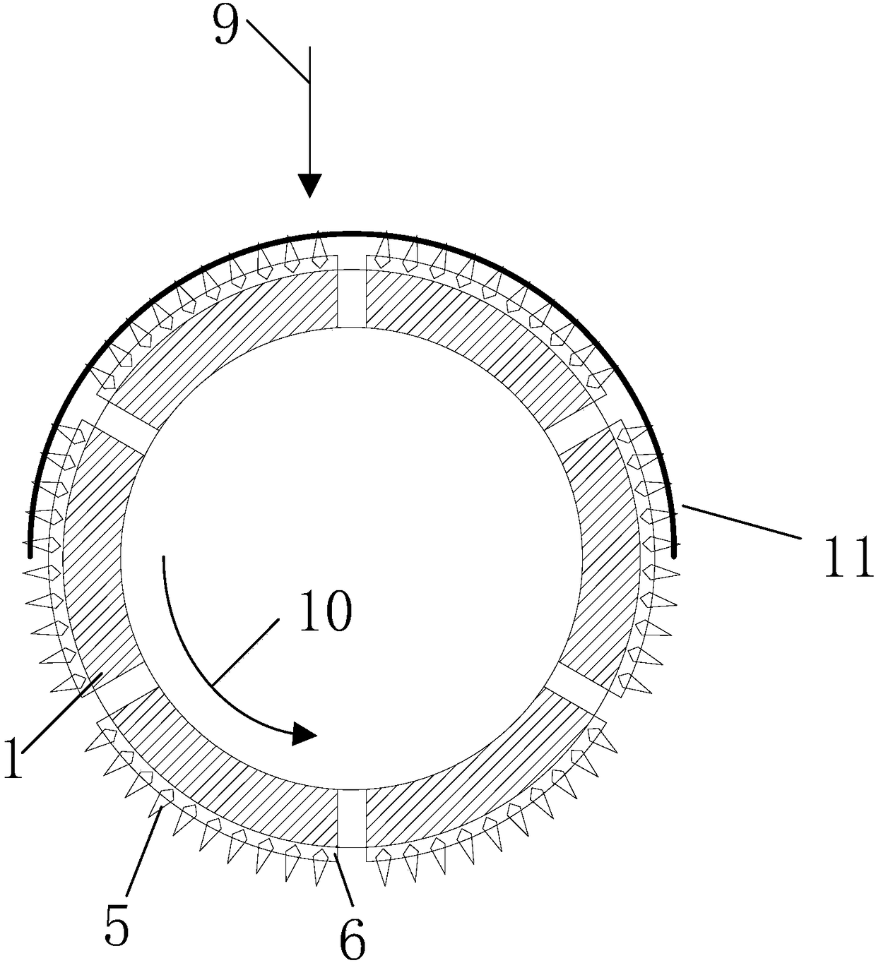
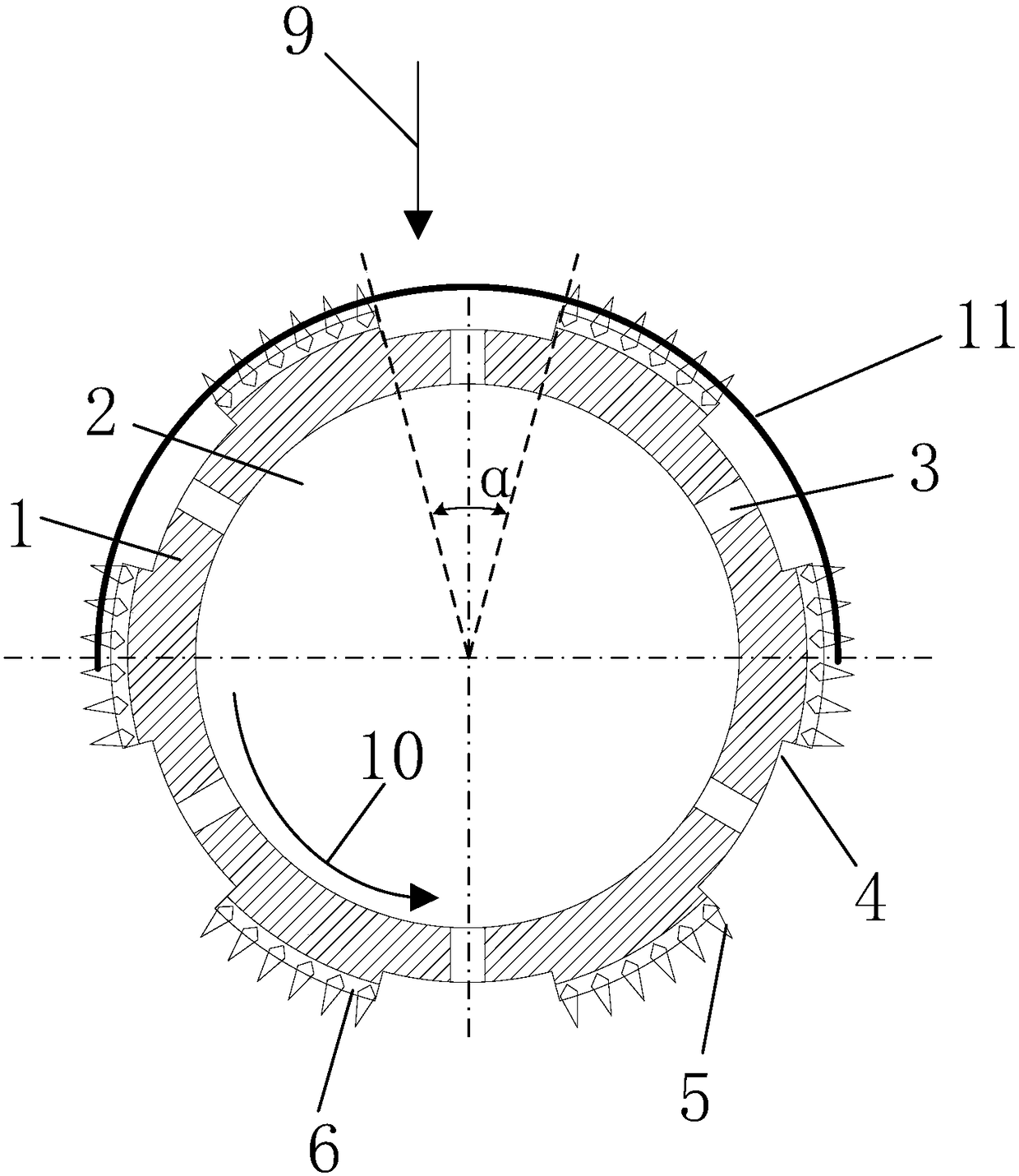
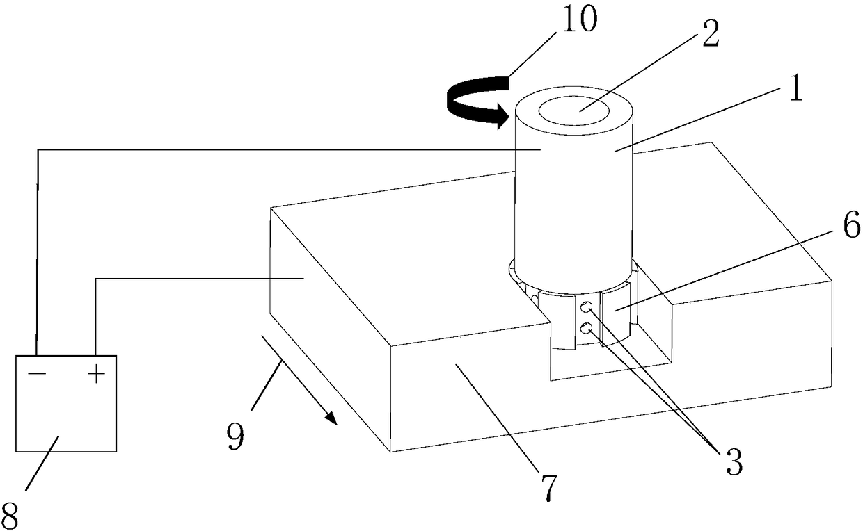
[0030] Such as figure 2 As shown, an electrolytic milling tool cathode with both efficiency and precision is characterized in that it includes a cathode base 1, an arc-shaped groove 4 and an insulating abrasive grain layer 6; the lower end of the side wall of the cathode base 1 is provided with several equal intervals Distributed arc-shaped grooves 4, the side walls of the non-groove walls are inlaid with diamond abrasive grains 5 through a resin bond to form an insulating abrasive grain layer 6; the center of the cathode substrate 1 is provided with a blind hole 2, and the arc-shaped groove 4 is provided with The spray hole 3 communicated with the blind hole 2.

[0031] Such as image 3 As shown, the method for using the negative electrode of the electrolytic milling and grinding processing tool with both efficiency and precision is characterized in that it includes the...


PUM


Abstract

The invention relates to an electrolytic milling-grinding machining tool cathode with efficiency and precision and an electrolytic milling-grinding method, and belongs to the field of electrolytic milling-grinding composite machining. According to the electrolytic milling-grinding machining tool cathode and the electrolytic milling-grinding method, a plurality of arc-shaped grooves at equal intervals are formed in the lower end of the side wall of the tool cathode, the side walls of the grooves are insulated, and diamond abrasive particles are inlaid in the wall surfaces of the portions, except for the grooves, of the side wall of a cathode base body through a resin binder, so that electrochemical anodic dissolution only exists in the surfaces of the portions, opposite to the grooves, of aworkpiece, at the moment, the depths of the grooves become a part of a machining gap, accordingly the contact depth between the diamond abrasive particles in the portions, except for the grooves, ofthe side wall of the cathode base body and the machining surface of the workpiece is increased, then the grinding effect of the diamond abrasive particles on the workpiece in the electrolytic milling-grinding process is enhanced, and the precision and the surface quality of the electrolytic milling-grinding machining can be improved; and moreover, compared with the electrolytic milling-grinding finish machining under the low current density in the past, the tool cathode can adopt higher current density, and the machining efficiency can be improved.

Description

technical field [0001] The invention relates to an electrolytic milling and grinding tool cathode and an electrolytic milling method that take into account both efficiency and precision, and belongs to the field of electrolytic milling and grinding combined processing. Background technique [0002] With the development of science and technology, parts made of difficult-to-cut materials such as titanium alloys and high-temperature alloys have been used more and more in the fields of aviation, aerospace, petroleum, and chemical industry. For example, artificial earth satellites, manned spacecraft, space shuttles, etc. are gradually using titanium alloy plate weldments. In deep well mining of oil and natural gas, corrosion-resistant and wear-resistant superalloys must be used. However, due to the high hardness and low thermal conductivity of these materials, traditional machining is often accompanied by problems such as large cutting force, high temperature in the cutting area,...

Claims


Application Information

Patent Timeline
Patent Type & Authority Applications(China)
IPC IPC(8): B23H5/10B23H5/08
Inventor 岳小康曲宁松牛屾李寒松
Owner NANJING UNIV OF AERONAUTICS & ASTRONAUTICS
Learn More