Machining device

a technology of machining device and machining tool, which is applied in the direction of manufacturing tools, grinding machine components, metal-working machine components, etc., can solve the problems of damage to tool t, and no longer detectable change in contact state, so as to prevent damage to the tool and deterioration in machining accuracy

Inactive Publication Date: 2006-01-26
GIRO GH +1
View PDF5 Cites 17 Cited by
  • Summary
  • Abstract
  • Description
  • Claims
  • Application Information

AI Technical Summary

Benefits of technology

[0008] An object of the present invention is to provide a machining device capable of machining appropriately by monitoring and controlling a contact state between a workpiece and a tool as well as of preventing damage on the tool and deterioration in machining accuracy.

Problems solved by technology

With the machining device, the approach and the contact of the workpiece and the tool can be detected, however, once the workpiece contact the tool, the change in the contact state may no longer be detected.
Even though there is generated the change in the above contact state, the rapid increase of the load cannot be corrected according to the above machining device described in the Document, and the cutting is forcedly performed with the excessive cutting load, thus resulting in disadvantages such as damage on the tool T and the deterioration in machining accuracy.

Method used


Image

  • Machining device
  • Machining device
  • Machining device

Examples


first embodiment

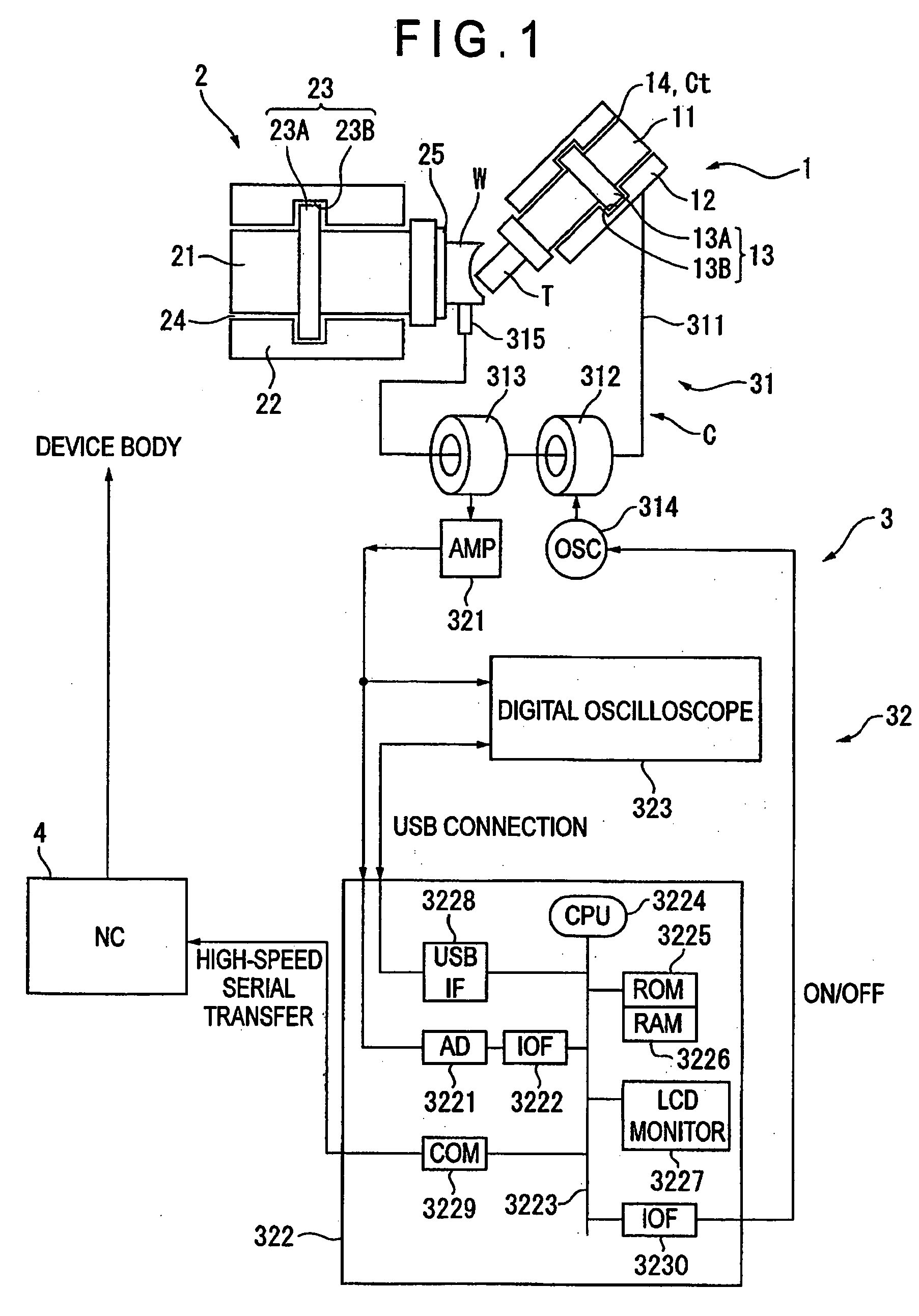
[0050]FIG. 1 shows a machining device according to a first embodiment of the present invention.

[0051] The machining device performs cutting of a workpiece W with use of a tool T by rotating the tool T and the workpiece W. The tool T is made of conductive metal. The tool T may be an end mill formed with a nib and a cutting blade, or may be a grinding stone for finishing a machining surface. The tool T includes various kinds of tools different in their profiles, so that a user can select the optimum one considering the purpose of machining. In a case of the workpiece W, the one having conductivity, for example, the one made of steel is selected.

[0052] The tool T is detachably attached to a tool rotation driver 1 for rotating the tool T. - The tool rotation driver 1 includes a main spindle 11 as a substantially columnar tool holder provided to rotate around an axis line (central axis), and a main spindle housing 12 as a first outer peripheral portion formed to cover an outer peripher...

second embodiment

[0086] Next, a second embodiment of the present invention will be described. The same numeric numbers are applied to components identical with or corresponding to that described in the first embodiment for omitting or simplifying the description (in a third, fourth, fifth or sixth embodiment as well).

[0087] As shown in FIG. 3, in a machining device according to a second embodiment of the present invention, the insulation 25 interposed between the workpiece W and the workpiece shaft 21 in the first embodiment is removed, so that the workpiece W is electrically connected to the workpiece shaft 21 directly. The other end of the conductor 311 is directly attached to the workpiece shaft housing 22. Assume that the -workpiece shaft 21 and the workpiece shaft housing 22 are conductive.

[0088] According to the above configuration, when the tool T contacts the workpiece W in machining, a closed-circuit C is formed in a counterclockwise direction in FIG. 3, the closed-circuit connecting the ...

third embodiment

[0091] Next, a third embodiment of the present invention will be described.

[0092] As shown in FIG. 4, in a machining device according to the present embodiment, a personal computer (PC) 5 is provided instead of the LCD monitor 3227 of the first embodiment. The personal computer 5 exchanges data with the controller 322 by a signal of USB. Similar to the first embodiment, on a display screen (a display) of the personal computer 5, there are displayed thresholds S1 and S2 regulating an allowable output range of the digital signal from the AD converter 3221 next to the output value of the actual digital signal. Further, the various pieces of auxiliary information and the various auxiliary conditions for monitoring the contact state can also be displayed.


PUM

PropertyMeasurementUnit
surface roughnessaaaaaaaaaa
conductiveaaaaaaaaaa
electricallyaaaaaaaaaa

Abstract

According to a machining device for machining a conductive workpiece (W) by a conductive (T), when the tool (T) contacts the workpiece (W) in machining, there is formed a closed-circuit (C) connecting the tool (T), the workpiece (W), a brush (315), a conductor (311), a main spindle housing (12), a main spindle (11) and again the tool (T in that order. Alternating-current is inducted to the closed-circuit (C) by a high-frequency generator (314) and an exciting coil (312). As a contact state between the tool (T) and the workpiece (W), impedance of the closed-circuit (C) is changed and then the alternating-current is changed, so that induction current is generated at a detector coil (313), thus monitoring and controlling the contact state by way of the induction current. Since a light contact state can constantly be maintained in machining according to a monitoring condition including a light/heavy contact-determining threshold, cutting resistance will not increase, thereby preventing damage on the tool (T) and deterioration in machining accuracy.

Description

BACKGROUND OF THE INVENTION [0001] 1. Field of the Invention [0002] The present invention relates to a machining device. In particular, the present invention relates to a machining device capable of machining while monitoring and controlling a contact state between a workpiece and a tool. [0003] 2. Description of Related Art [0004] Conventionally, there has been known a machining device described in Document: JP H10-217069A (on pages 4, 5, 8 and FIGS. 1, 2). [0005] The machining device includes a machine body, a table attached to the machine body for setting a workpiece thereon, a main spindle for attaching a tool which machines the workpiece, a contact bearing interposed between the machine body and the main spindle for rotatably supporting the main spindle, a feeding electrode coaxially disposed to face the main spindle with a minute gap, and a conductor for electrically connecting the machine body with the feeding electrode. The machine body, the table, the main spindle and the f...

Claims


Application Information

Patent Timeline
Patent Type & Authority Applications(United States)
IPC IPC(8): B24B49/00B23Q17/09
CPCB24B49/16Y10T408/16Y10T408/173Y10T408/13B23Q15/12B23Q15/14B23Q17/00
Inventor YAMANE, YASUOFUKUTA, MASAHIKOSHIRANE, OSAMU
Owner GIRO GH
Why Eureka
Try Eureka