
Antenna fixing structure of magnetron for microwave oven

A fixed antenna and magnetron technology, applied in the field of magnetron, can solve problems such as the inability to effectively reduce the second harmonic wave of the magnetron, deterioration of electromagnetic compatibility characteristics, and adverse effects of electrical components, so as to improve electromagnetic compatibility characteristics, The effect of reducing the second harmonic and improving the stability

Inactive Publication Date: 2014-12-31
LG ELECTRONICS (TIANJIN) APPLIANCES CO LTD
View PDF6 Cites 1 Cited by
  • Summary
  • Abstract
  • Description
  • Claims
  • Application Information

AI Technical Summary

Problems solved by technology

[0015] However, the antenna fixing structure of the magnetron used in the microwave oven in the prior art cannot effectively reduce the second harmonic wave of the magnetron, thereby degrading the electromagnetic compatibility characteristics of the magnetron used in the microwave oven, thereby causing damage to the human body and electrical components around the microwave oven. Negative Effects

Method used


Image

  • Antenna fixing structure of magnetron for microwave oven
  • Antenna fixing structure of magnetron for microwave oven
  • Antenna fixing structure of magnetron for microwave oven

Examples


Embodiment Construction

[0030] The present invention will be described in detail below in conjunction with the accompanying drawings and embodiments.

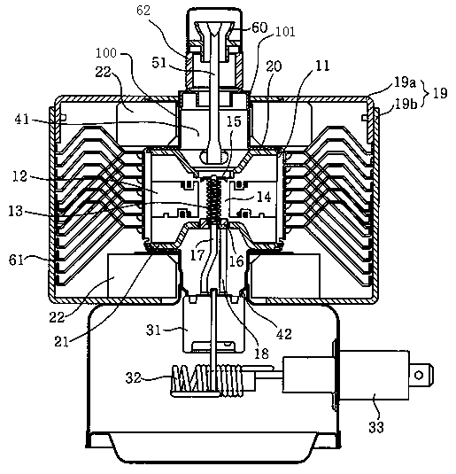
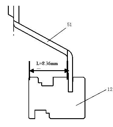
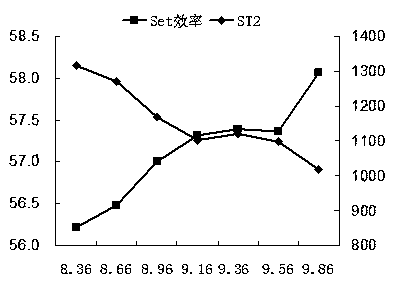
[0031] Figure 4 It is a schematic diagram of the antenna fixing structure of the magnetron for microwave oven of the present invention; Figure 5 It is a schematic diagram of the relationship between the fixed position of the magnetron antenna for microwave ovens and the efficiency and stability of filtering the second harmonic obtained from the experiment; Image 6 It is a schematic diagram of 6δ management of the antenna fixing structure of the magnetron for microwave oven of the present invention.

[0032] like Figure 4 As shown, the antenna fixing structure of the magnetron for microwave oven of the present invention includes the blade 12 arranged inside the antenna 51 and the magnetron positive electrode part, and the upper end of the antenna is coaxial with the central axis of the magnetron positive electrode part and runs through the magnet...


PUM


Abstract

The invention relates to an antenna fixing structure of a magnetron for a microwave oven. The antenna fixing structure comprises an antenna and blades arranged inside the positive electrode portion of the magnetron. The upper end of the antenna and the central shaft of the positive electrode portion of the magnetron are arranged coaxially; the upper end of the antenna passes through an antenna sealing cover and a ceramic ring of the magnetron and is connected with an upper sealing portion of an exhaust pipe. And the lower end of the antenna bends towards the outer side of the central shaft of the positive electrode portion and is fixedly with the blades mutually; and the distances between the inner sides of the blades and the antenna lower end and the blade fixing positions are increased by 10 to 15%. Because the fixing position of the antenna lower end is farther off the central shaft of the positive electrode portion of the magnetron, the electromagnetic compatible characteristic of the magnetron for the microwave oven can be improved under the circumstances that the magnetron characteristic remains unchanged, thereby reducing the secondary harmonics well.

Description

technical field [0001] The invention belongs to the technical field of magnetrons, and in particular relates to an antenna fixing structure of a magnetron for a microwave oven that improves the electromagnetic compatibility characteristics of the magnetron while keeping the characteristics of the magnetron unchanged. Background technique [0002] figure 1 It is a longitudinal sectional view of a magnetron structure in the prior art; figure 2 is a structural schematic diagram of the position of the magnetron exhaust pipe in the prior art; image 3 It is a schematic diagram of the 6δ management of the antenna fixing structure of the magnetron used in the microwave oven in the prior art. [0003] like Figure 1 to Figure 2 As shown, the magnetron mainly includes: a positive electrode part; a negative electrode part; a magnetic pole part; a microwave transmitting part. The anode part consists of a barrel-shaped anode casing 11, on the inner wall of the anode casing 11, a pl...

Claims


Application Information

Patent Timeline
Patent Type & Authority Applications(China)
IPC IPC(8): H01J23/40
Inventor 李斌
Owner LG ELECTRONICS (TIANJIN) APPLIANCES CO LTD
Learn More