T beam mould moving device and use method thereof

A technology of shifting formwork and beam side formwork, applied in the direction of mold, bridge, bridge construction, etc., can solve the problems of large manpower and material cost, prolonged construction period, low overall efficiency, etc., to save manpower and material resources, and reduce the risk. , the effect of improving efficiency

Active Publication Date: 2015-01-07
JIANGSU SHENGLE CONSTR ENG CO LTD
View PDF10 Cites 17 Cited by
  • Summary
  • Abstract
  • Description
  • Claims
  • Application Information

AI Technical Summary

Problems solved by technology

[0002] As an important part of rail transit infrastructure construction, T-beam has the characteristics of saving concrete, light weight, and strong spanning ability. In the pouring of T-beam, molds are needed. The mold is composed of side formwork, bottom formwork and end formwork, etc. The formed steel mold is heavy. At present, in the process of constructing the T-beam, it is necessary to repeat the demoulding and closing the mold many times. In this process, it needs to consume a lot of manpower and material resources. Due to the complete manual operation, the overall The efficiency is relatively low, which leads to the extension of the construction period and the high construction cost of the project, and because the side mold has a relatively large weight, there is still a certain degree of operational risk. Higher, more convenient device for demoulding and clamping operations

Method used


Image

  • T beam mould moving device and use method thereof
  • T beam mould moving device and use method thereof
  • T beam mould moving device and use method thereof

Examples


Embodiment 1

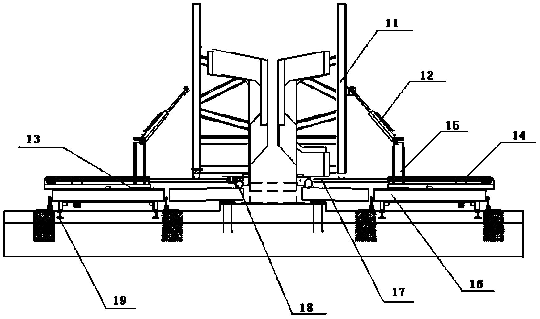
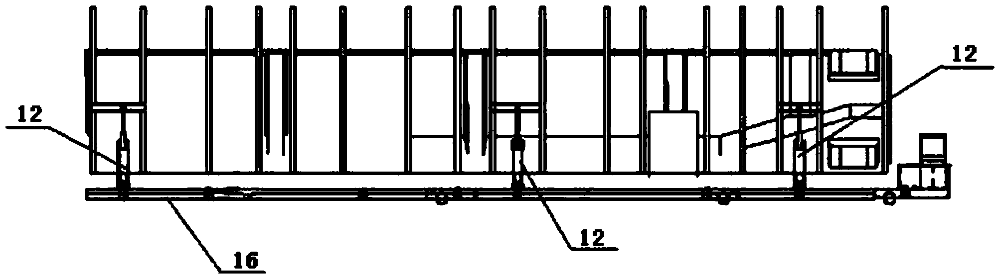
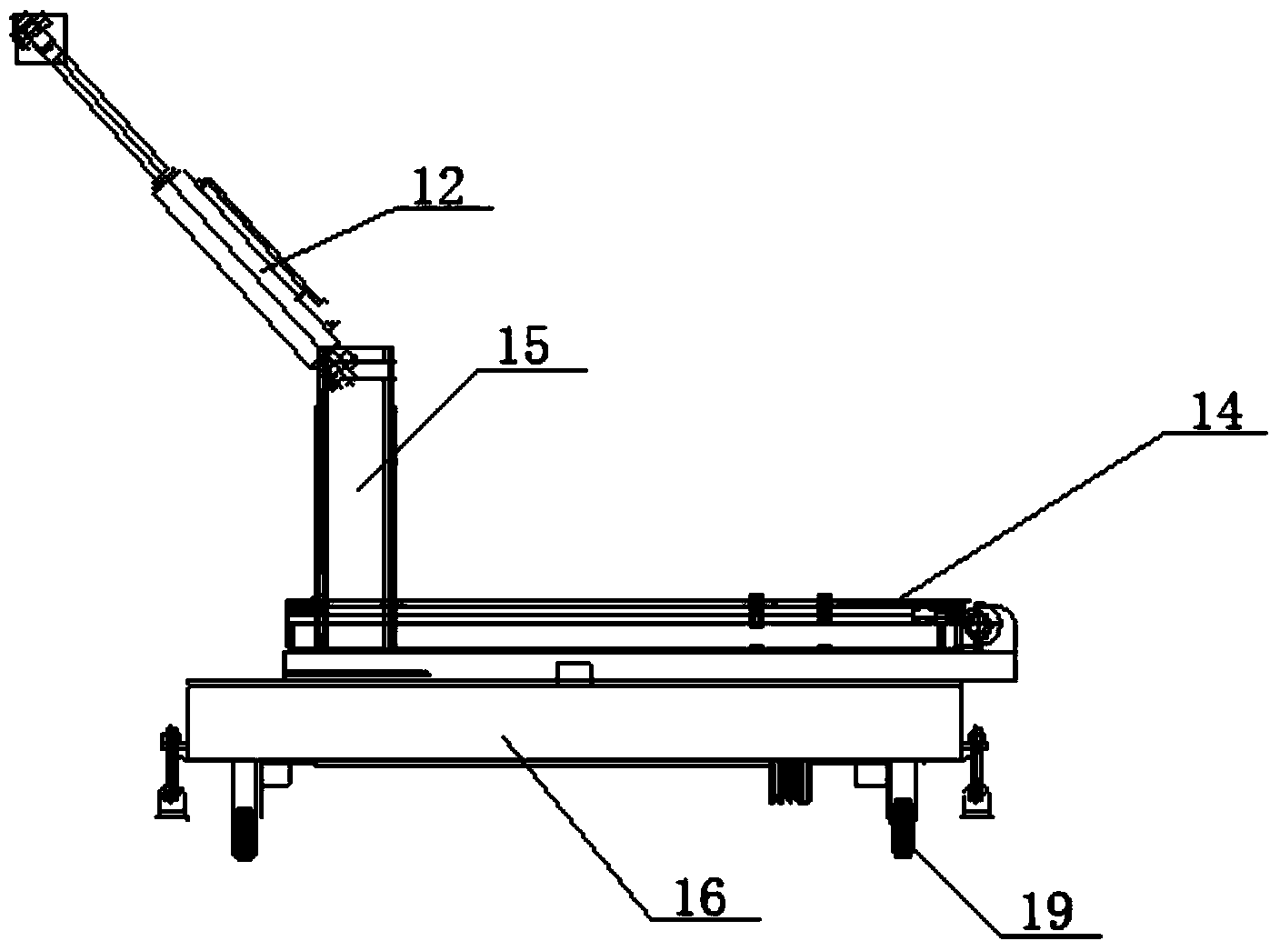
[0035] Such as figure 1 The schematic diagram of the structure of the T-beam mold-moving device of the present invention is shown, including a T-beam side mold 11, a cable-stayed cylinder 12, a slide rail 13, a flat-pull cylinder 14, a fixed end 15, a mold-moving trolley 16, an overlapping plate 17, and a pulley block 18, guide wheel 19, protrusion 20, groove 21, pin hole 22, slideway 23.

[0036] For a T-beam construction site, rails are respectively laid on both sides of the T-beam side form 11, and a mold-moving trolley 16 is set on the track, wherein the lower surface of the mold-moving trolley 16 is provided with a guide wheel 19, which is realized by the sliding action of the guide wheel 19. The movement of the mold shifting trolley 16 on the track, the traction power unit of the mold shifting trolley 16 can be a reel type electric flat car, a storage battery flat car and a gasoline engine flat car, wherein the preferred gasoline engine and battery drive combination form...


PUM


Abstract

The invention discloses a T beam mould moving device and a specific use method thereof. A track is laid on each side of a T beam side mould; each track is provided with a mould moving trolley; the upper surface of each mould moving trolley is provided with a plurality of bidirectional adjustment devices; each horizontal drawing oil cylinder is arranged at a position adjacent to the corresponding bidirectional adjustment devices. According to the T beam mould moving device and the specific use method, the demoulding and mould clamping efficiency of the T beam side mould is improved due to each mould moving trolley and the parts which are arranged on the upper portion of the mould moving trolley and the bottom of the T beam side mould is provided with a pulley block, the surface of a lapping plate is provided with a sliding channel, the pulley block and the sliding channel are corresponding to each other, the friction force in the movement process of the T beam side mould is converted into the rolling friction, and accordingly the service life of the T beam side mould is extended.

Description

technical field [0001] The invention relates to an auxiliary tool for traffic infrastructure construction, in particular to a T-beam mold-moving device and a specific use method. Background technique [0002] As an important part of rail transit infrastructure construction, T-beam has the characteristics of saving concrete, light weight, and strong spanning ability. In the pouring of T-beam, molds are needed. The mold is composed of side formwork, bottom formwork and end formwork, etc. The formed steel mold is heavy. At present, in the process of constructing the T-beam, it is necessary to repeat the demoulding and closing the mold many times. In this process, it needs to consume a lot of manpower and material resources. Due to the complete manual operation, the overall The efficiency is relatively low, which leads to the extension of the construction period and the high construction cost of the project, and because the side mold has a relatively large weight, there is still...

Claims


Application Information

Patent Timeline
Patent Type & Authority Applications(China)
IPC IPC(8): B22D33/02
CPCB28B7/0002B28B7/0029E01D21/00
Inventor 汤德良
Owner JIANGSU SHENGLE CONSTR ENG CO LTD
Why Eureka
Try Eureka