Over mold structure used for long and thin region on tool handle

A handle, slender technology, applied in the field of mold structure of injection molding products, can solve the problems of low injection molding pressure, large pressure loss, prone to trapped air, etc., to solve the exhaust problem, prevent glue overflow, and improve the quality of the product.

Active Publication Date: 2015-01-07
ZHANGJIAGANG ZHONGTIAN PRECISION MOLDING +1
View PDF5 Cites 2 Cited by
  • Summary
  • Abstract
  • Description
  • Claims
  • Application Information

AI Technical Summary

Benefits of technology

This patented technology prevents excessive glues from sticking out during production by creating an impervious layer between two parts called a sealed area with brushings or other means for easy removal when needed. Additionally, this design helps reduce trace material left behind after separation while still maintaining strong bond strength at both ends.

Problems solved by technology

This technical issue addressed in this patents relates to improving the comfortable handling properties of handheld tools used during production processes while also ensuring proper functioning over time without damaging their outer surfaces or causing issues like leakages from imperfections caused by excessive force applied through gears. Existing methods involve adding extra materials into the injector systems themselves, making them difficult to work around and subject to wear out quickly after being filled. Additionally, existing solutions require significant space within the machine housing where they can accumulate debris, reducing efficiency.

Method used


Image

  • Over mold structure used for long and thin region on tool handle
  • Over mold structure used for long and thin region on tool handle
  • Over mold structure used for long and thin region on tool handle

Examples


Embodiment Construction

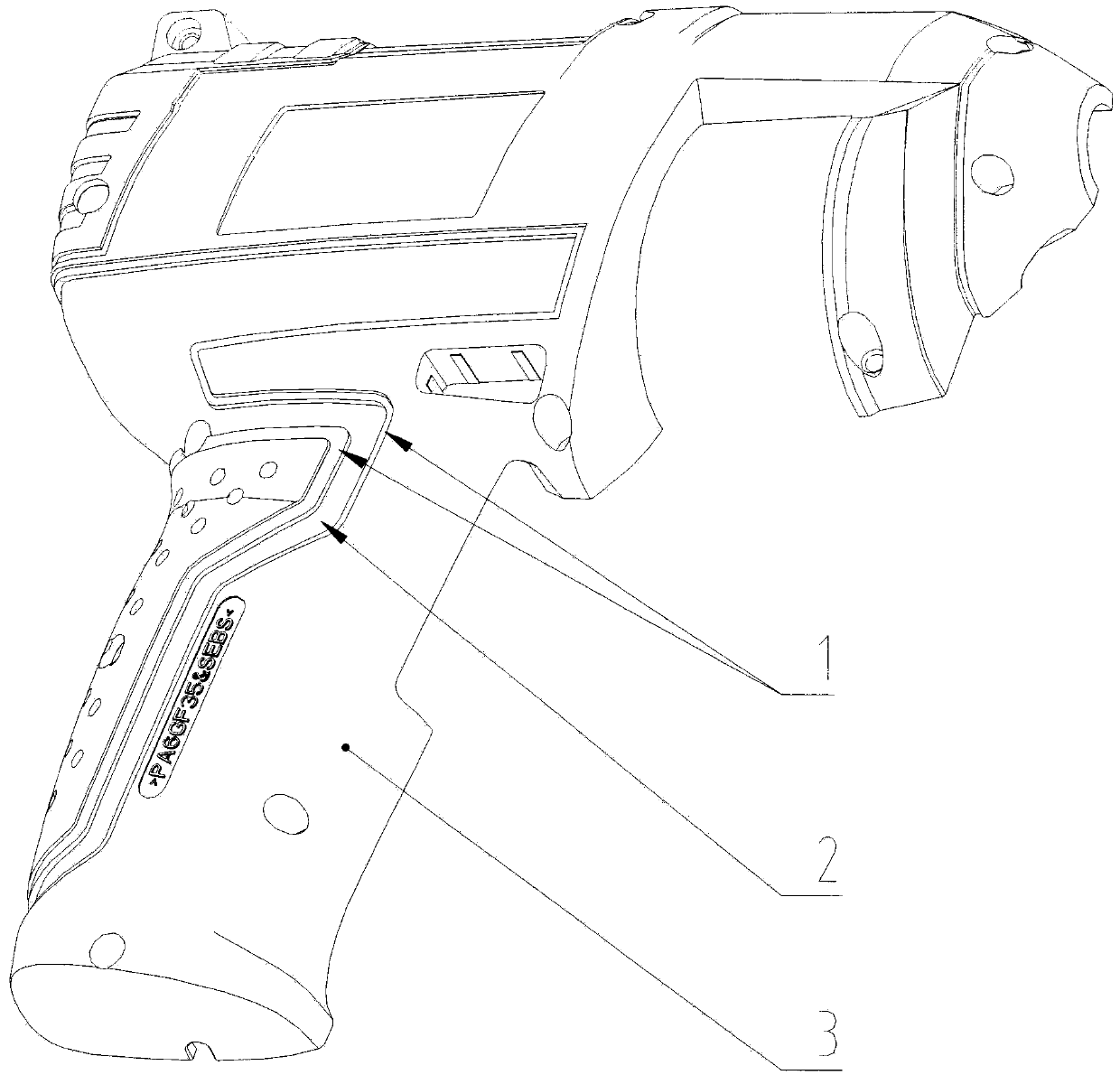
[0013] The present invention will be further described below in conjunction with the accompanying drawings and the embodiment of the right half tool handle.

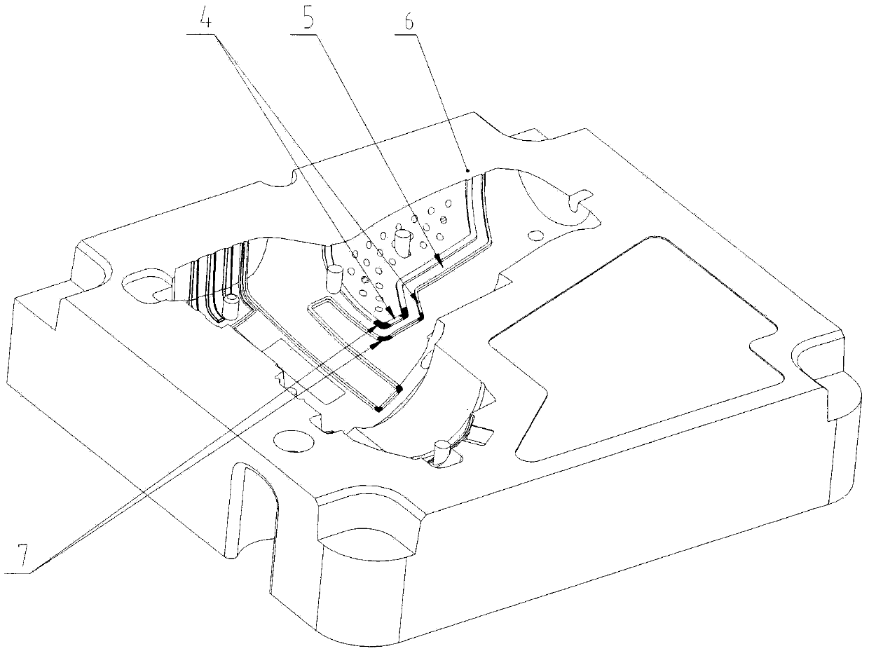
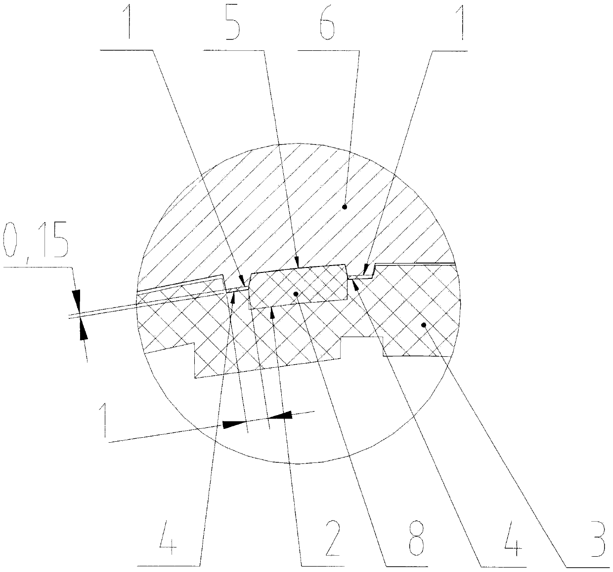
[0014] Such as figure 1 , figure 2 and image 3 As shown, a body cavity surface 2 is provided on the part of the hard rubber body 3 that needs to be coated with soft rubber on the hard rubber body 3 of the right half tool handle, and a sealing groove 1 is opened on both sides of the body cavity surface 2; 6, the corresponding position that needs to be coated with soft glue is provided with a fixed mold core cavity surface 5, and both sides of the fixed mold core cavity surface 5 are provided with a sealing glue position 4. The raised height dimension of the sealing position 4 and the corresponding concave depth dimension of the sealing groove 1 are an interference fit when the mold is closed, so as to prevent the soft rubber 8 from overflowing during secondary injection molding.

[0015] Such as figure 2 As shown, ...


PUM

PropertyMeasurementUnit
Widthaaaaaaaaaa

Abstract

The invention relates to an over mold structure used for a long and thin region on a tool handle. The over mold structure comprises a hard rubber body of the handle, a fixed mold insert, glue-sealing slots, rubber-sealing positions, breathable steel inserts, a body cavity surface and a fixed mold insert cavity surface. The convex height size of the rubber-sealing positions and the corresponding concave depth size of the glue-sealing slots are in interference fit when the mold is clamped, so that a pressing force is generated between the fixed mold insert rubber-sealing positions and the glue-sealing slots corresponding to a product hard rubber body after the mold is clamped; the rubber-sealing position in an air-trapping portion of the fixed mold insert cavity is in a breathable steel mosaic structure, and joint surfaces of the breathable steel inserts and corresponding rubber-sealing positions are in close fit. The over mold structure has the beneficial effects that excessive glue is prevented through interference fit of the rubber-sealing positions; the exhaust problem is overcome by the close fit of the breathable steel inserts; parting line traces at enchased parts on a product surface is lightened; and excellent and good rate of products is increased.

Description


Claims


Application Information

Patent Timeline
Owner ZHANGJIAGANG ZHONGTIAN PRECISION MOLDING
Why Eureka
Try Eureka