a syringe for anesthesia

A technology of syringes and injection tubes, applied in the field of medical devices, can solve problems such as the inability to determine and control the depth of needle insertion, easy occurrence of medical accidents, unstable syringes, etc., to reduce medical risks, reduce medical accidents, and facilitate injection operations Effect

Inactive Publication Date: 2018-06-05
THE AFFILIATED HOSPITAL OF QINGDAO UNIV
View PDF15 Cites 0 Cited by
  • Summary
  • Abstract
  • Description
  • Claims
  • Application Information

AI Technical Summary

Problems solved by technology

[0002] The syringe usually consists of a syringe with a small hole at the front end and a matching piston core rod. When the core rod is pulled out, the liquid or gas is sucked from the small hole at the front end of the syringe, and the liquid or gas is squeezed out when the core rod is pushed in. It is found that the existing syringes are manually fixed directly by hand, and then directly inserted into the human body for injection. The injection process is also fixed manually. For example, a Chinese patent discloses "an anesthesia syringe" (authorized announcement number: CN 202128764 U), The patent includes a syringe, a needle set on the top of the syringe and a piston rod for pushing the injection liquid. The syringe is composed of an inner syringe and an outer syringe, and a cooling liquid is arranged between the inner syringe and the outer syringe. The piston The method of sliding connection between the rod and the inner wall of the inner syringe achieves the operation of the syringe. The disadvantages of the above patent are: it is not stable when used, non-professionals cannot use it normally, and the exhaust is very troublesome, and it is inevitable that there will be problems even if professionals use it. Mistakes will cause the instability of the syringe, which is prone to medical accidents, and it is easy to waste liquid medicine when using exhaust, and it is impossible to determine and control the depth of needle insertion during use. When the insertion is too deep, it is easy for the patient to feel severe pain. Painful, and when it is too shallow, it cannot achieve the desired effect

Method used


Image

  • a syringe for anesthesia
  • a syringe for anesthesia

Examples


Embodiment Construction

[0016] Below in conjunction with accompanying drawing and embodiment of description, specific embodiment of the present invention is described in further detail:

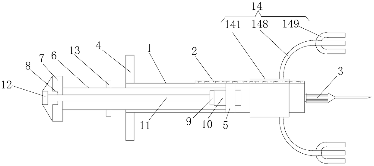
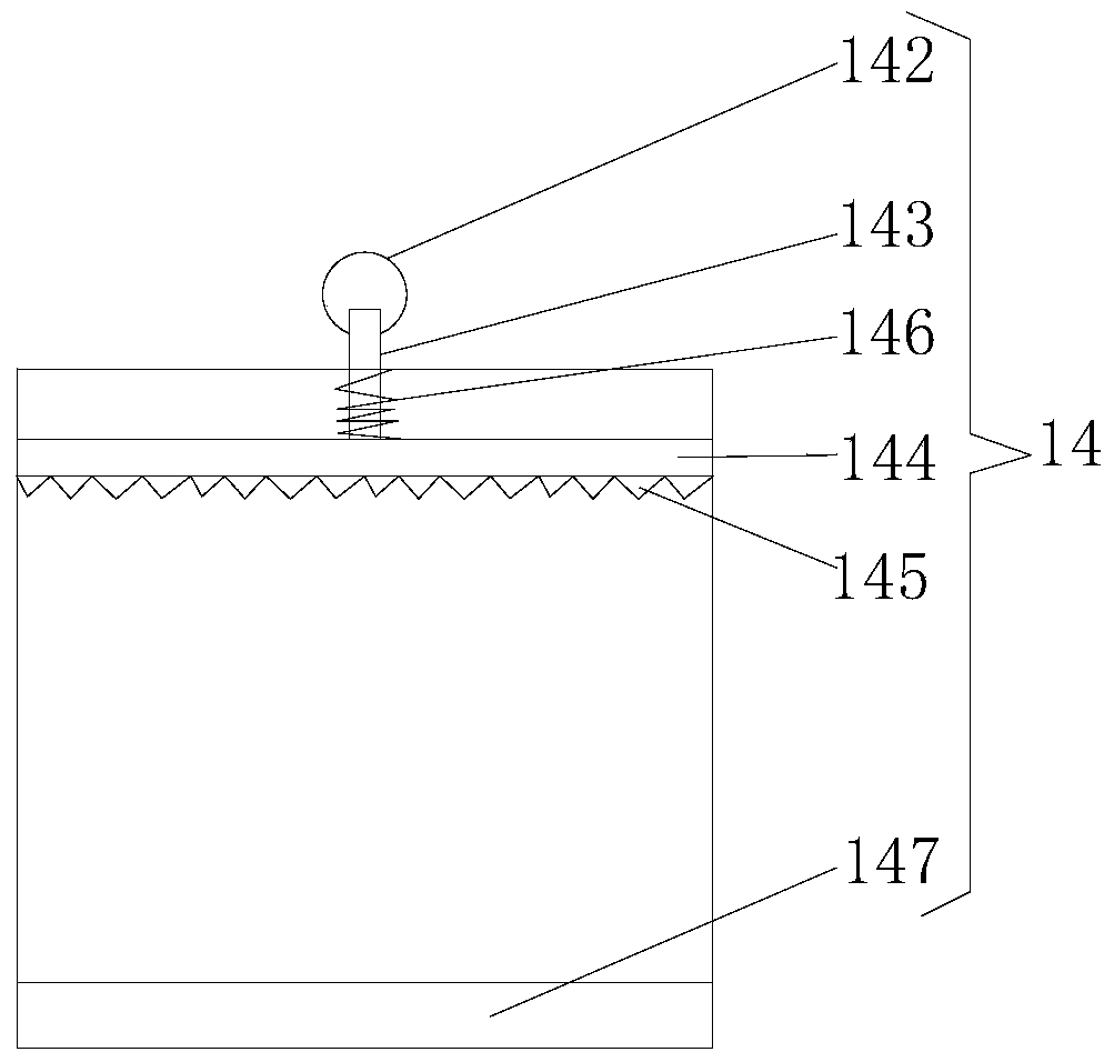
[0017] see Figure 1-2 , the present invention provides a technical solution: a syringe for anesthesia, comprising an injection tube 1, a scale plate 2 is fixedly installed on the top of the injection tube 1, by setting the scale plate 2, the effect of controlling the insertion depth of the needle 3 is achieved, The fixed position of the fixing device 14 can be controlled by the scale disc 2, so that when the needle head 3 is inserted, the depth of insertion can be clearly known, and the depth of insertion of the needle head 3 can also be well controlled. Teeth 145 match the positioning groove, one end of the injection tube 1 is fixedly connected with the needle 3, the connection between the needle 3 and the injection tube 1 is provided with a sealing rubber ring, the other end of the injection tube 1 is provided wi...


PUM


Abstract

The invention discloses an injector for anesthesia. The injector comprises an injection tube, wherein a scale plate is fixedly arranged at the top of the injection tube; a needle is fixedly connected to one end of the injection tube, and an opening is formed in the other end of the injection tube; a holding handle is arranged at the top of the opening of the injection tube; a No.1 piston is arranged inside the injection tube; the inner wall of the injection tube is movably connected to the right end of a first push rod by virtue of the No.1 piston; the left end of the first push rod penetrates through the opening and extends outside the injection tube; the left end of the first push rod is fixedly connected to one side of the first handle; and a groove is formed in the other side of the first handle. By setting a fixing device, the injector for anesthesia can achieve an effect of fixing the injection tube; by setting fixed teeth and an anti-slip layer inside the fixing device and by setting the scale plate, an effect of controlling the inserting depth of the needle is achieved; and by setting a pneumatic chamber, an effect of exhausting the injection tube is achieved.

Description

technical field [0001] The invention relates to the technical field of medical devices, in particular to a syringe for anesthesia. Background technique [0002] The syringe usually consists of a syringe with a small hole at the front end and a matching piston core rod. When the core rod is pulled out, the liquid or gas is sucked from the small hole at the front end of the syringe, and the liquid or gas is squeezed out when the core rod is pushed in. It is found that the existing syringes are manually fixed directly by hand, and then directly inserted into the human body for injection. The injection process is also fixed manually. For example, a Chinese patent discloses "an anesthesia syringe" (authorized announcement number: CN 202128764 U), The patent includes a syringe, a needle set on the top of the syringe and a piston rod for pushing the injection liquid. The syringe is composed of an inner syringe and an outer syringe, and a cooling liquid is arranged between the inner...

Claims


Application Information

Patent Timeline
Patent Type & Authority Patents(China)
IPC IPC(8): A61M5/178A61M5/31
Inventor 梁永新程华伟宋建防魏明
Owner THE AFFILIATED HOSPITAL OF QINGDAO UNIV
Why Eureka
Try Eureka