Mold core insert for mold, mold and machining process of mold

A processing technology and insert technology, applied in the field of core inserts and processing technology, to achieve the effect of simple assembly process, beneficial to die-casting production, and improved quality

Active Publication Date: 2020-02-21
ZHUHAI RUNXINGTAI ELECTRICAL
View PDF7 Cites 0 Cited by
  • Summary
  • Abstract
  • Description
  • Claims
  • Application Information

AI Technical Summary

Problems solved by technology

[0007] The present invention aims to solve the problems described above

Method used


Image

  • Mold core insert for mold, mold and machining process of mold
  • Mold core insert for mold, mold and machining process of mold
  • Mold core insert for mold, mold and machining process of mold

Examples


Embodiment Construction

[0038] In order to make the purpose, technical solutions and advantages of the embodiments of the present invention clearer, the technical solutions in the embodiments of the present invention will be clearly and completely described below in conjunction with the drawings in the embodiments of the present invention. Obviously, the described embodiments It is a part of embodiments of the present invention, but not all embodiments. Based on the embodiments of the present invention, all other embodiments obtained by persons of ordinary skill in the art without making creative efforts belong to the protection scope of the present invention. It should be noted that, in the case of no conflict, the embodiments in the present application and the features in the embodiments can be combined arbitrarily with each other.

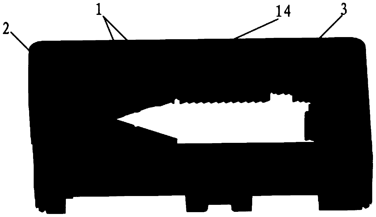
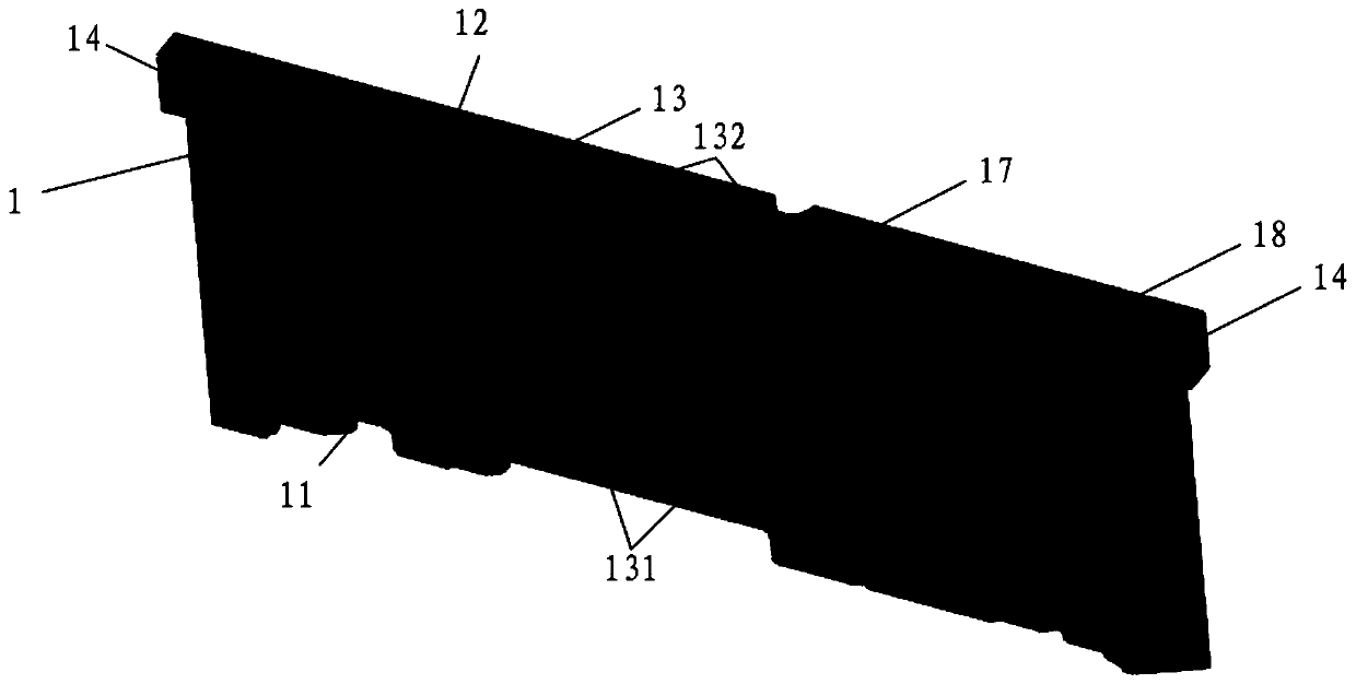
[0039] The core insert for the mold, the mold and the processing technology of the mold according to the present invention will be described in detail below with refer...


PUM


Abstract

The invention provides a mold core insert for a mold, the mold and a machining process of the mold. The mold core insert comprises a product forming cavity, an ejector pin position, at least one exhaust groove and insert hanging tables. The product forming cavity is formed in one end of one side face of the mold core insert. The ejector pin position communicates with the product forming cavity andis arranged at the other end of one side face of the mold core insert. One end of each exhaust groove communicates with the product forming cavity, and the other end of each exhaust groove communicates with one end face of the mold core insert. The insert hanging tables are arranged on the two sides of one end of the mold core insert and used for positioning the mold core insert and the mold in the Z-axis direction. The machining time of the mold is shorter than that of a traditional electrode discharge machining time, mold saving and polishing are facilitated after the deep portion and the narrow gap portion of the cavity are separated, die-casting production is facilitated, and meanwhile, the quality of castings is improved, and the machining cost of the mold is reduced.

Description

technical field [0001] The invention relates to the technical field of mold manufacturing, in particular to a mold core insert for a mold, a mold and a mold processing technology. Background technique [0002] The mold opening time and cost of the existing die-casting molds are concentrated on the mold core. For example, for a die-casting mold with a heat sink structure, due to the deep mold cavity and narrow gap, the graphite electrode is generally firstly molded, and then the graphite electrode is used in the electrode. The disadvantages of processing the heat sink cavity on the spark machine are: [0003] 1) EDM consumes a lot of man-hours, and EDM patterns on thin and deep cavity walls require a lot of time to save mold; [0004] 2) Due to the limitation of the mold-saving tool, the deepest part cannot be mold-saving, so that the roughness of the deeper part and the narrower gap cannot meet the requirements, that is, the mold-saving polishing is difficult; [0005] 3) ...

Claims


Application Information

Patent Timeline
Patent Type & Authority Applications(China)
IPC IPC(8): B22D17/24B23P15/24
CPCB22D17/24B23P15/24
Inventor 张莹饶龙瑾任怀德
Owner ZHUHAI RUNXINGTAI ELECTRICAL
Why Eureka
Try Eureka