Photographing device with light quantity adjustment

a technology of light quantity and photographing device, which is applied in the field of photographing device, can solve the problems of inability to directly process the scene to be photographed before, dull shadow or washed highlight, and inability to achieve the effect of preventing the increase of cost and short processing tim

Inactive Publication Date: 2007-07-17
FUJIFILM HLDG CORP +1
View PDF6 Cites 46 Cited by
  • Summary
  • Abstract
  • Description
  • Claims
  • Application Information

AI Technical Summary

Benefits of technology

[0014]An object of the present invention is therefore to provide a photographing device such as a digital still camera or a video camera, which can solve the above problems and in which an image of a scene having a large light quantity ratio, such as a backlight scene or a stroboscopic scene in which a light quantity ratio of a main subject to a background is large, is suitably photographed, a cost is prevented from increasing,, and a processing time is short.
[0016]Preferably, the light quantity adjustment unit is a unit for relatively reducing a light quantity of an area corresponding to a bright portion of the image of the subject when the image is taken by the photographing unit.

Problems solved by technology

Thus, in the case where the backlight scene in which the light quantity of a main subject is insufficient against a background is photographed by using the CCD image pickup element or the like, the main subject to be photographed becomes a dark portion (shadow) or the background becomes a bright portion (highlight) in a photographed image, thus leading to dull shadow or washed-out highlight.
In the case of the stroboscopic scene, the main subject becomes a bright portion (highlight) or the background becomes a dark portion (shadow), thus leading to dull shadow or washed-out highlight.
It is impossible to directly process a scene to be photographed before it is photoelectrically read.
Besides, since such an image processing device is very expensive, although a trader who receives a request for print output can possess it, it is very difficult for an individual to possess it.
However, since this image pickup device must include a plurality of image pickup elements corresponding to the respective divided incident lights, a device for dividing the incident light, a device for synthesizing images read by the respective image pickup elements, and the like, there are problems that the image pickup device itself becomes complicated, a cost becomes high, and a time required for processing image data becomes long.

Method used


Image

  • Photographing device with light quantity adjustment
  • Photographing device with light quantity adjustment
  • Photographing device with light quantity adjustment

Examples


Embodiment Construction

[0042]Hereinafter, a photographing device of the present invention will be described on the basis of preferred embodiments illustrated in the accompanying drawings.

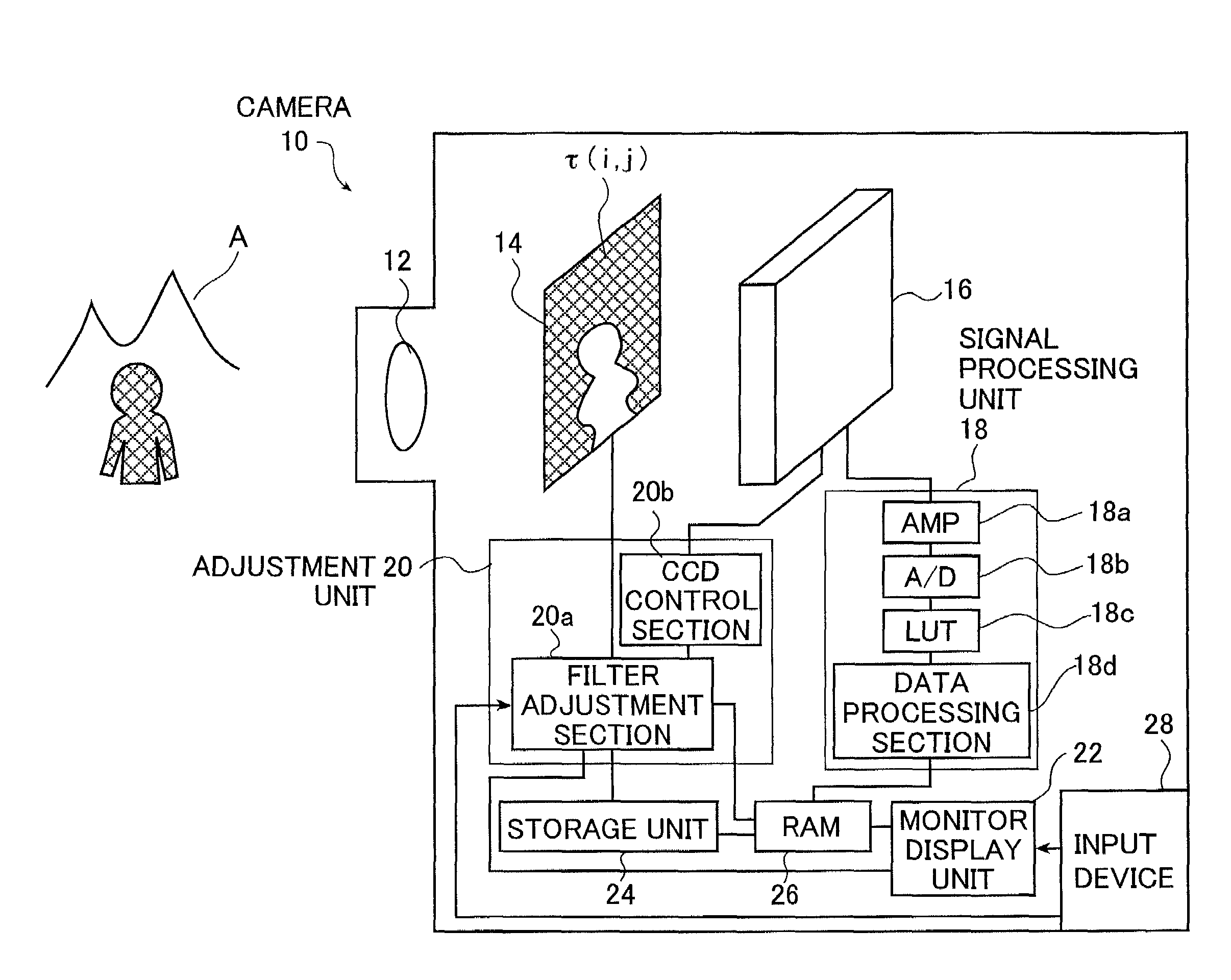
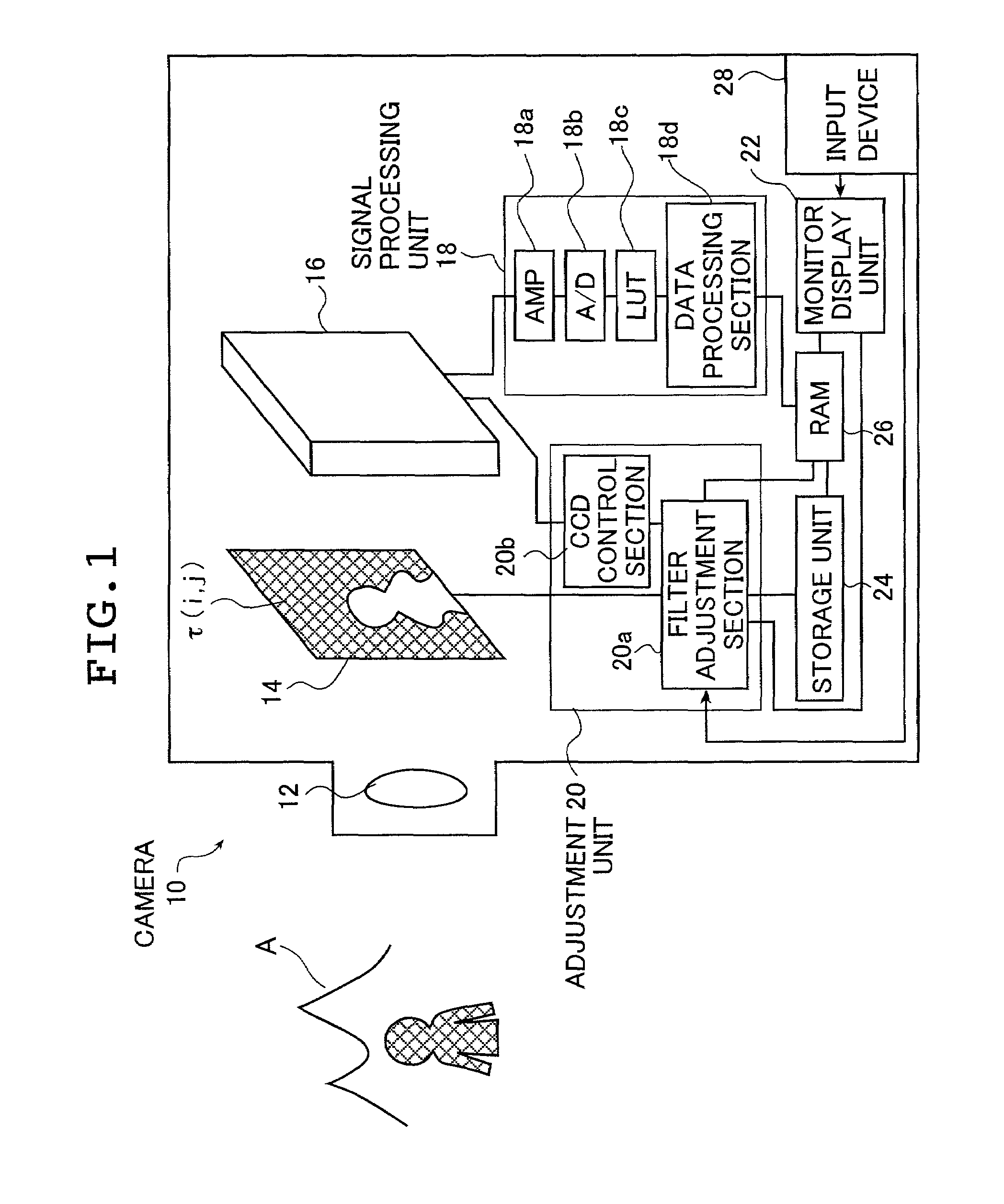
[0043]FIG. 1 is a structural view of a digital still camera (hereinafter referred to as a camera) 10 as a preferred embodiment of a photographing device of the present invention. Incidentally, the photographing device of the present invention is not limited to the digital still camera as illustrated in this embodiment, but may be a video camera for taking a motion picture or a conventional analog camera for taking a picture by using a photosensitive material such as a silver salt film.

[0044]The camera 10 is a single plate image pickup device, and mainly includes an image pickup lens 12, a liquid crystal filter 14 for partially changing the light intensity of incident light carrying an optical image of a subject A (FIG. 1 shows a photo subject of a backlight scene in which a background is bright and a main subject is dark)...


PUM


Abstract

The photographing device includes an optical lens, a photographing unit for taking an image of a subject imaged through the optical lens and a light quantity adjustment unit for partially adjusting a light quantity of the image of the subject. The light quantity adjustment unit is provided in an optical path of light carrying the image of the subject and between the optical lens and the photographing unit.

Description

BACKGROUND OF THE INVENTION[0001]1. Field of the Invention[0002]The present invention relates to a photographing device for taking a photo of an image having a large light quantity ratio while a light quantity adjustment is partially made, and particularly to a photographing device, such as a digital still camera or a digital video camera, using an image pickup element, such as a CCD (charge coupled device), capable of suitably recording an image having a large light quantity ratio.[0003]2. Description of the Related Art[0004]At present, as a device for recording an image, a digital still camera, a video camera or the like is used in a wide range. In such a digital still camera or a video camera, a CCD image pickup element for outputting an output signal on the basis of the quantity of electric charge stored in response to the quantity of light received in a definite time, a CMOS image pickup element, or the like is mainly used, and the obtained output signal is A / D converted, so th...

Claims


Application Information

Patent Timeline
Patent Type & Authority Patents(United States)
IPC IPC(8): H04N5/238H04N5/225H04N5/235
CPCH04N5/2254H04N5/235H04N5/238H04N23/70H04N23/75
Inventor YAMAGUCHI, HIROSHI
Owner FUJIFILM HLDG CORP
Why Eureka
Try Eureka