Two-step method resource treatment process for sludge containing oil

A treatment process and resource recovery technology, which is applied in the field of oily sludge two-step resource recovery process

Inactive Publication Date: 2012-08-08
SHAANXI UNIV OF SCI & TECH
View PDF10 Cites 42 Cited by
  • Summary
  • Abstract
  • Description
  • Claims
  • Application Information

AI Technical Summary

Problems solved by technology

The same solidification method does not recover useful petroleum resources

Method used


Image

  • Two-step method resource treatment process for sludge containing oil
  • Two-step method resource treatment process for sludge containing oil

Examples


Embodiment 1

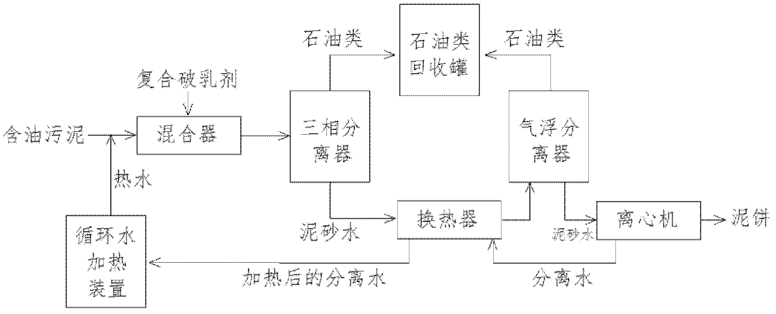
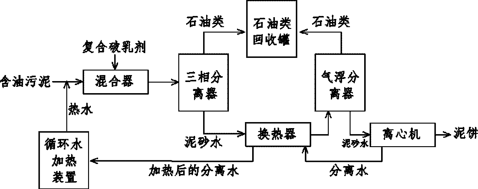
[0036] The oily sludge obtained from Oil Production Plant A contains 38.5% oil, 51.9% solids and 9.6% water. The oily sludge after removal of impurities is melted with 4 times the volume of hot water, mixed with a compound demulsifier and then entered into a three-phase separator. The conditions in the three-phase separator are controlled as follows: temperature 70°C, pH=5.5, compound demulsifier concentration 3‰, stirring speed 200r / min, hydraulic retention time 20min. The crude oil in the upper layer is recovered, and the cement-sand mixture in the lower layer enters the air flotation separation tank for air flotation separation, and the hydraulic retention time of the air flotation separation tank is 15 minutes. After recovering the crude oil in the upper layer, the mud cake in the lower layer was centrifuged and the oil content was 1.8%, the water content was 32.1%, and the solid content was 66.1%. The recovery rate of crude oil was calculated to be 95.3%.

Embodiment 2

[0038] It is taken from the oily sludge of Oil Extraction Plant B, which contains 41.7% oil, 49.4% solid matter, and 8.9% water. The oily sludge after removing impurities is dissolved with 3 times the volume of hot water, and the mixed liquid is mixed with the compound demulsifier and then enters the three-phase separator. The conditions in the three-phase separator are controlled as follows: temperature 70°C, pH=7, compound demulsifier concentration 3‰, stirring speed 150r / min, hydraulic retention time 20min. The crude oil in the upper layer is recovered, and the cement-sand mixture in the lower layer enters the air flotation separation tank for air flotation separation, and the hydraulic retention time of the air flotation separation tank is 15 minutes. After recovering the crude oil in the upper layer, the mud cake in the lower layer contains 0.6% oil, 38.7% water and 60.7% solids after centrifugation of the mud-water mixture in the lower layer. The calculated oil recovery ...

Embodiment 3

[0040] The oily sludge obtained from Oil Production Plant C contains 30.5% oil, 55.9% solids and 13.6% water. The oily sludge after removing impurities is dissolved with 4 times the volume of hot water, and the mixed solution is mixed with the compound demulsifier and then enters the three-phase separator. The conditions in the three-phase separator are controlled as follows: temperature 70°C, pH=8, compound demulsifier concentration 3‰, stirring speed 300r / min, hydraulic retention time 20min. The crude oil in the upper layer is recovered, and the cement-sand mixture in the lower layer enters the air flotation separation tank for air flotation separation, and the hydraulic retention time of the air flotation separation tank is 15 minutes. After recovering the crude oil in the upper layer, the mud-water mixture in the lower layer was centrifuged and the mud cake contained 1.5% oil, 36.7% water and 61.8% solids, and the calculated oil recovery rate was 95.1%.


PUM


Abstract

A two-step method resource treatment process for sludge containing oil is composed of two steps of hot emulsion breaking phase separation and normal temperature air float separation. Sludge containing oil is melted with hot water with the volume of 2-5 times of the volume of the sludge, mixed liquid is in a fluidized state, the mixed liquid of the sludge containing oil is mixed with a compound emulsion breaking agent through a mixer to enter a three-phase separator, and three-phase separation of oil, sludge and water is achieved by slowly stirring the mixed liquid. Oil in a fluidized state atthe upper layer overflows out of the separator to enter an oil recycling tank, and sludge-water mixed water at the lower layer is cooled by a heat exchanger A to enter the air float separator to be separated at the normal temperature. Oil at the upper layer of the air float separator enters the oil recycling tank, and sludge-water mixed liquid at the lower layer is sent into a centrifugal machineto perform sludge-water separation. Series cucumber planting tests show that mud cake soil has good effects on germination and growth of cucumber seeds.

Description

technical field [0001] The invention belongs to the field of petroleum environmental protection, and in particular relates to a two-step resource recovery process for oily sludge. Background technique [0002] Oily sludge refers to the oily solid waste produced in the process of oil extraction, transportation, refining and oily sewage treatment. The composition of oily sludge is very complex, generally composed of oil-in-water, water-in-oil, and suspended solid impurities. It is an extremely stable suspended emulsion system, containing a large amount of aged crude oil, wax, asphaltene, colloid, and suspended solids , bacteria, salts, acid gas, corrosion products, etc., also includes a large number of coagulants, corrosion inhibitors, scale inhibitors, bactericides and other water treatment agents added in the production process. Due to the complex composition and difficult separation, the treatment and recycling of oily sludge is one of the problems in the petroleum industr...

Claims


Application Information

Patent Timeline
Patent Type & Authority Applications(China)
IPC IPC(8): C02F11/00C02F11/12C10G1/00
Inventor 孙根行司军滕青刘若阳付炜路建平
Owner SHAANXI UNIV OF SCI & TECH
Why Eureka
Try Eureka