PU sheet downwards-moving type foaming production process and device

A technology of production equipment and production process, which is applied in the field of PU sheet downward-moving foaming production process and its production equipment, can solve the problems of poor compressive strength in the middle part and large density gradient of foaming process, etc., and achieve the improvement of large density gradient, The effect of simplifying operation steps and saving staffing

Pending Publication Date: 2020-10-09
LIYANG SHANHU IND CO LTD
View PDF0 Cites 0 Cited by
  • Summary
  • Abstract
  • Description
  • Claims
  • Application Information

AI Technical Summary

Problems solved by technology

[0004] The purpose of the present invention is to provide a downward-moving foaming production process for PU sheets, which effectively improves the problems of large density gradient and poor compressive strength in the middle of the original foaming process.

Method used


Image

  • PU sheet downwards-moving type foaming production process and device
  • PU sheet downwards-moving type foaming production process and device
  • PU sheet downwards-moving type foaming production process and device

Examples


Embodiment 1

[0048] Embodiment 1: A kind of PU sheet material down-moving foaming production process comprises the following processing steps:

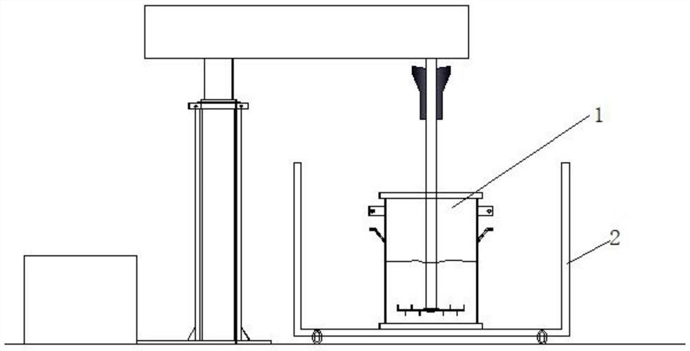
[0049] S1. Turn on the laser light, align the cross light with the scale line of the lifting platform 4, then move the foam box 2 to the top of the lift platform 4, adjust the position of the foam box so that the cross light coincides with the scale line 21, and pass through the casters Fix the foaming box 2; turn on the servo motor to raise the lifting platform 4, push the movable bottom plate 3 in the foaming box 2 to move upward, and rise to the position of 75% of the total height of the foaming box 2;

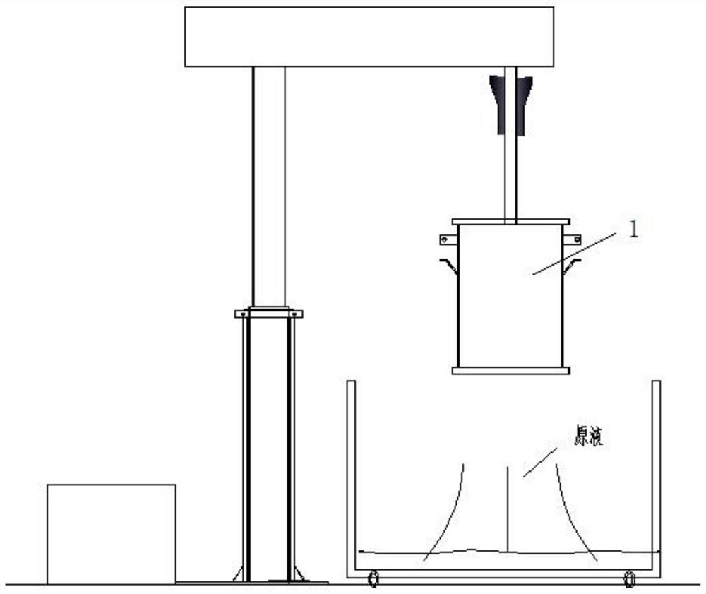
[0050] S2. Lay kraft paper on the movable bottom plate 3, then add the stock solution in the box-type foaming machine 1, after the stirring is completed, lift the box-type foaming machine 1 upwards, so that the foaming liquid is filled with the movable bottom plate 3 of the foaming box 2, and start Foaming;

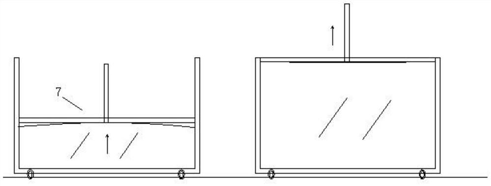
[0051] S3. When the foam foam rise...

Embodiment 2

[0053] Embodiment 2: A kind of PU sheet material down-moving foaming production process comprises the following processing steps:

[0054] S1. Turn on the laser light, align the cross light with the scale line of the lifting platform 4, then move the foam box 2 to the top of the lift platform 4, adjust the position of the foam box so that the cross light coincides with the scale line 21, and pass through the casters Fix the foaming box 2; turn on the servo motor to raise the lifting platform 4, push the movable bottom plate 3 in the foaming box 2 to move upward, and rise to the position of 70% of the total height of the foaming box 2;

[0055] S2. Lay kraft paper on the movable bottom plate 3, then add the stock solution in the box-type foaming machine 1, after the stirring is completed, lift the box-type foaming machine 1 upwards, so that the foaming liquid is filled with the movable bottom plate 3 of the foaming box 2, and start Foaming;

[0056] S3. When the foam foam rise...


PUM

PropertyMeasurementUnit
densityaaaaaaaaaa
densityaaaaaaaaaa
densityaaaaaaaaaa

Abstract

The invention discloses a PU sheet downwards-moving type foaming production process. The process includes the following steps of S1, positioning a foaming box over a lifting platform, then moving a movable bottom plate in the foaming box upwards through the lifting platform to the position, 65-75% of the total height, of the foaming box; S2, adding a stock solution into a box type foaming machineto be stirred, and then lifting the box type foaming machine to make foaming liquid fulfill the movable bottom plate of the foaming box to start foaming; S3, lowering the lifting platform and meanwhile making the movable bottom plate start to move down when foam rises to the position 25-35% of the height so that residual materials can foam downwards; and S4, when foaming of foam is completed, making a pin mechanism pierce into kraft paper between the bottom of the foam and the movable bottom plate for exhausting to finally obtain a foam body with a rectangular section. By means of the downwards-moving type box type foaming process, the problems of high density gradient and poor middle compression strength of an existing foaming process are effectively solved, and the problem that existingbottom density is high and exceeds the standard is also effectively solved.

Description

technical field [0001] The invention belongs to the technical field of PU foaming production, and in particular relates to a PU sheet downward-moving foaming production process and production equipment thereof. Background technique [0002] In the automotive interior parts industry, the production process of PU sheets for ceiling materials is generally a box-type foaming method, and then the foam blocks are sliced ​​by a slicer. In the box-type foaming process, the process of bottomless mixing tank is the mainstream, such as Figure 1~2 As shown, the bottom of the mixing tank has a sealing ring close to the bottom of the box. After the stock solution is stirred in the barrel, the mixing barrel is lifted from the bottom of the box. The stock solution flows on the bottom of the box and foams to fill the box. The final foam is obtained as the foaming liquid rises freely. , due to the resistance of the side plates around the foaming box, the top of the free-foaming foam has obvi...

Claims


Application Information

Patent Timeline
Patent Type & Authority Applications(China)
IPC IPC(8): B29C44/02B29C44/34B29K75/00
CPCB29C44/02B29C44/34B29C44/35B29K2075/00
Inventor 李国铭
Owner LIYANG SHANHU IND CO LTD
Why Eureka
Try Eureka