

Electromagnetic punching machine with punched hole detection device
A detection device and electromagnetic technology, applied in punching machines, manufacturing tools, metal processing, etc., can solve the problems of easy breakage of punches, failure of punching holes, complicated structure, etc., and achieve the effect of accelerating heat dissipation
Patent Information
- Authority / Receiving Office
- CN · China
- Patent Type
- Applications(China)
- Current Assignee / Owner
- Publication Date
- 2015-01-07
- Estimated Expiration
- Not applicable · inactive patent
Smart Images
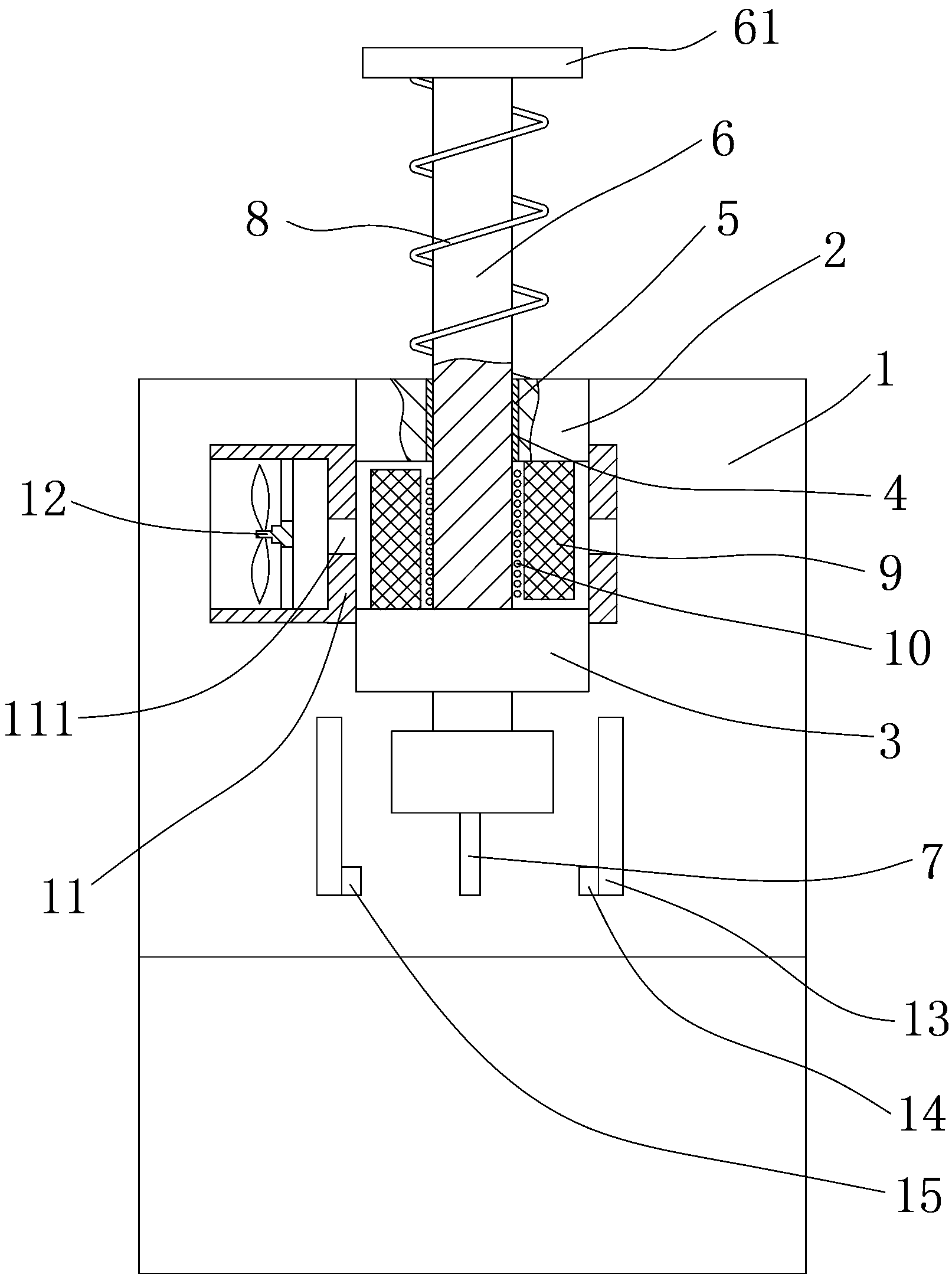
Figure 1
Abstract
Description
technical field
[0001] The invention relates to the technical field of punching machines, in particular to an electromagnetic punching machine with a punching detection device. Background technique
[0002] Punch production is mainly for sheet metal. Through the mold, blanking, punching, forming, deep drawing, trimming, fine blanking, shaping, riveting and extrusion parts can be made, which are widely used in various fields. Existing punch presses generally drive the flywheel through the motor, and the flywheel drives the punch to punch, or the hydraulic system controls the punch to punch, the structure is relatively complicated, and the manufacturing cost is relatively high. When stamping small holes, because the punch of the stamping die is thin, the punch is easy to break during stamping, or the punch may not be opened due to wear and other reasons, but now the plate punching process generally uses The automatic feeding device continuously feeds the material, and worker...
Examples
Embodiment Construction
[0009] The present invention will be described in further detail below in conjunction with accompanying drawing and specific embodiment: see figure 1 , an electromagnetic punching machine with a punching detection device, including a machine tool body 1, an upper fixed block 2 and a lower fixed block 3 are arranged in the body 1, and the upper fixed block 2 and the lower fixed block 3 are both A through hole 4 is provided, and a slide rail 5 is arranged in the through hole 4, and a stamping rod 6 is slid on the slide rail 5, and an upper mold 7 is connected to the bottom of the stamping rod 6, and the upper end of the stamping rod 6 A flange 61 is provided, an elastic member 8 is arranged below the flange 61, the lower part of the elastic member 8 is against the upper fixing block 2, and a plurality of magnets 9 are arranged around the outside of the stamping rod 6, and the stamping rod 6 6. A wire 10 is wound around the middle, and a shell 11 is set on the outside of the magn...