
Driver Controller Test System and Its Test Method

A driver controller and test system technology, applied in electrical testing/monitoring, etc., can solve the problems of inability to detect multiple handles, incapable of continuous automatic movement, inability to switch loads, etc., to achieve convenient viewing and printing, accurate and reliable load access , good effect of human-machine interface

Active Publication Date: 2017-09-26
HEBEI UNIV OF TECH
View PDF3 Cites 0 Cited by
  • Summary
  • Abstract
  • Description
  • Claims
  • Application Information

AI Technical Summary

Problems solved by technology

[0004] The technical problem to be solved by the present invention is to provide a driver controller test system and its test method, wherein the driver controller test system is a detection system composed of software and hardware, and its test method can be automatically completed according to the flow process specified by the test requirements The test of the contact performance of the driver controller contact and the current output performance of the angular positioner can be combined with the actual application to switch the load, parameter setting can be performed, and it also has a data correction function. During the test, each contact can be monitored individually. At the same time, a large amount of test data can be recorded and can be queried at any time, which overcomes the existing technology that can only perform a simple and single closing operation on the contact of the driver controller and then detect it, and cannot continuously and automatically calibrate each calibration position of the driver controller. All the contacts are detected, and at the same time, continuous automatic movement cannot be performed in a situation close to the actual operation, the load cannot be switched, and the detection of multiple handles cannot be realized.

Method used


Image

  • Driver Controller Test System and Its Test Method
  • Driver Controller Test System and Its Test Method
  • Driver Controller Test System and Its Test Method

Examples


Embodiment 1

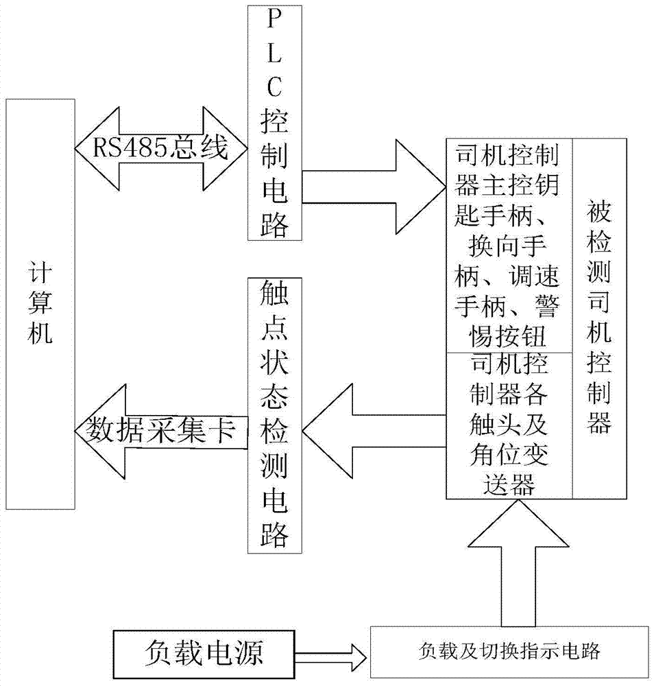
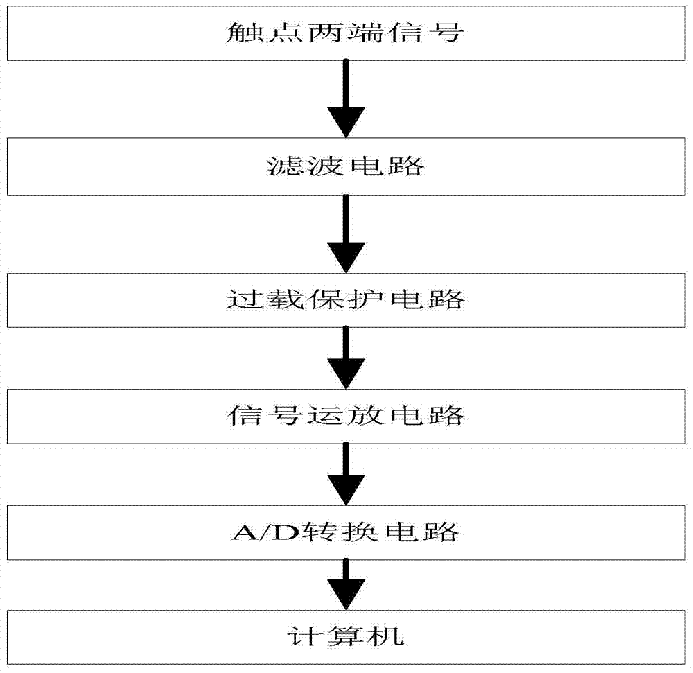
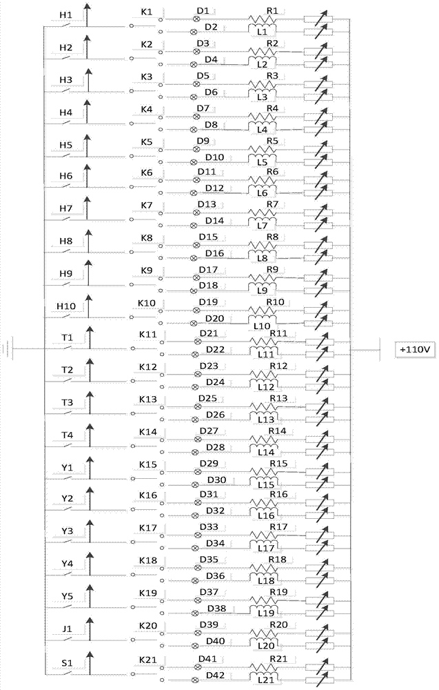
[0068] according to the above figure 1 , figure 2 , Figure 3(a), Figure 3(b), Figure 4 , Figure 5 , Figure 6 , Figure 7 , Figure 8 and Figure 9 The embodiment constitutes the driver controller test system used in this embodiment, adopts this system to test the contact contact performance and angle positioner current output performance test of the tested driver controller, and the tested driver controller includes 21 pairs of contacts and 1 Angle transmitter, the load is resistive load or inductive load, the operation steps are:

[0069] The first step is to double-click the "Test Program" icon to enter the login interface, enter the company name and operator name in the input box, and click the "Enter System" button to enter the system;

[0070] The second step is to enter the running main interface:

[0071] The operation mode of the main interface is: click the "Initialize" button, the interface will prompt whether it is in the initial position, and a paramete...


PUM


Abstract

The invention discloses a driver controller testing system and a testing method thereof, and relates to electric examination type monitoring of control systems or components of the control systems. The driver controller testing system comprises a hardware part and a software part. The hardware part mainly comprises a computer, a contact state detection circuit, a PLC circuit, a load power source, a load and switch indication circuit and a tested driver controller. The software part mainly comprises an initialization module, a test parameter setting module, a data correction module, a contact monitoring module, a test running control module and a test data querying module. The test on the contact performance of a driver controller contact and the current output performance of an angle position device is finished under the control of the computer. The driver controller testing system overcomes the defects that in the prior art, testing is carried out after only simple and single closing operation is conducted on the contact of a driver controller, it cannot be done to automatically and continuously test all contacts at all calibration positions of the driver controller, continuous and automatic running cannot be carried out under the situation close to the actual operation, the load cannot be switched, and a plurality of handles cannot be tested at the same time.

Description

technical field [0001] The technical solution of the present invention relates to the electrical inspection monitoring of the control system or its components, specifically the driver controller test system and its test method. Background technique [0002] The driver controller is an important control part of rail trains, and the performance of the driver controller determines the reliability and safety of the entire train operation. The test of the driver controller is an important means to ensure and improve the product quality of the driver controller, and the driver controller test system is the necessary equipment to complete the detection of the performance of the driver controller. [0003] CN203276019U discloses "EMU driver controller mechanical life test bench", CN202886988U discloses "driver controller test bench", CN203224779U discloses "electric locomotive driver controller test bench", CN203588067 reports "driver controller detection device", These existing te...

Claims


Application Information

Patent Timeline
Patent Type & Authority Patents(China)
IPC IPC(8): G05B23/02
CPCG05B23/02
Inventor 李文华梁成洋杨松赵靖英
Owner HEBEI UNIV OF TECH
Learn More