Method for distinguishing supersaturation state of signal intersections

A technology for intersection and state discrimination, applied in the field of transportation, can solve the problems of low discrimination accuracy and difficult to measure accurately, and achieve the effects of expanding functions, improving utilization efficiency, and improving accuracy and real-time performance.

Active Publication Date: 2015-01-07
严格集团股份有限公司
View PDF8 Cites 18 Cited by
  • Summary
  • Abstract
  • Description
  • Claims
  • Application Information

AI Technical Summary

Problems solved by technology

[0004] In order to solve the problem that the existing discrimination method mainly judges whether the intersection is in an oversaturated state based on the queue length, but the queue length changes dynamically

Method used


Image

  • Method for distinguishing supersaturation state of signal intersections
  • Method for distinguishing supersaturation state of signal intersections
  • Method for distinguishing supersaturation state of signal intersections

Examples


specific Embodiment approach 1

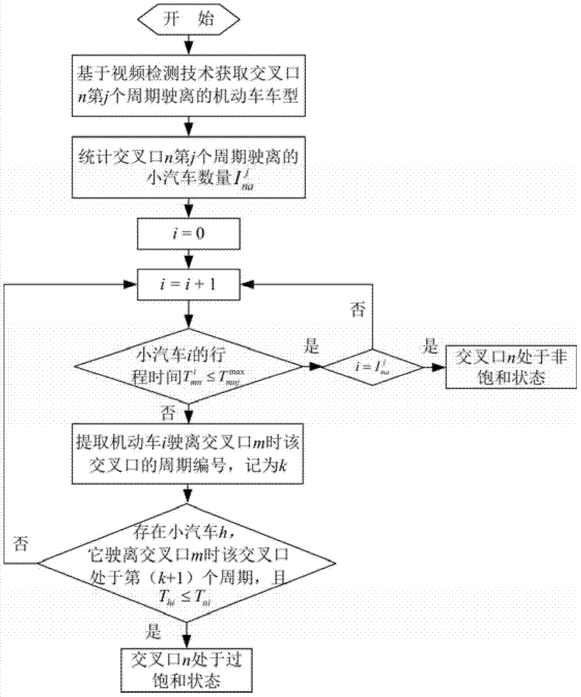
[0013] Specific implementation mode one: combine figure 1 and figure 2 Describe this embodiment, a kind of method for judging the oversaturation state of a signalized intersection described in this embodiment is realized through the following steps:

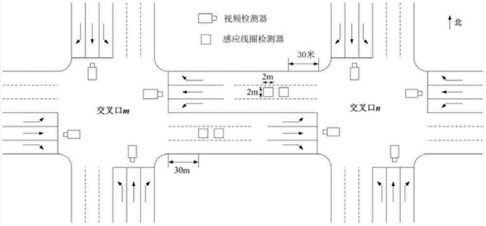
[0014] Step 1. Arrange a video detector at the stop line of each entrance of the signalized intersection, and arrange two induction coils consecutively 30 meters downstream of the intersection exit;

[0015] Step 2, collecting traffic flow data through video detectors and induction coil detectors arranged at each intersection and road section;

[0016] Step 3: In the traffic signal control system, set the signal machine at each signal intersection to store and execute the signal timing scheme;

[0017] Step 4, transmit the data collected by the detector and the signal timing plan stored in the signal machine at each signalized intersection to the traffic management center through the communication line;

[0018] Step 5. Ident...

specific Embodiment approach 2

[0019] Specific implementation mode two: combination figure 1 and figure 2 Describe this embodiment, in step 1 of a kind of method for judging the oversaturation state of a signalized intersection described in this embodiment, the video detector mainly collects the motor vehicle license plate and the traffic flow of the lane, and the induction coil detector mainly collects the average running speed of the motor vehicle on the road section. speed.

[0020] Other components and connections are the same as those in the first embodiment.

specific Embodiment approach 3

[0021] Specific implementation mode three: combination figure 1 and figure 2 To illustrate this embodiment, the signal timing scheme in Step 3 of a method for judging an oversaturation state at a signalized intersection in this embodiment includes phase sequence, cycle duration, green light time of each phase, and green light interval time.

[0022] Other components and connections are the same as those in the first embodiment.


PUM


Abstract

The invention relates to a distinguishing method, in particular to a method for distinguishing the supersaturation state of signal intersections, and aims at solving the problem that in the current distinguishing method, whether the intersection is in the supersaturation state or not is mainly distinguished according to the queuing length, and the queuing length dynamically changes under the influence of signal lamps, so that accurate measurement is difficult; as a result, the distinguishing precision is low. The method comprises the following steps: arranging a video detector at the stop line of each entrance of the signal intersection, and continuously arranging two induction coils at the position 30 m away from the down stream of the exit of the signal intersection; collecting traffic flow data through the video detectors and induction coil detectors arranged at intersections and road segments; transmitting the data collected by the detectors and signal timing plans stored by signal intersection annunciators to a transport management center through communication lines; distinguishing the state of the intersections. The method is used in the field of transportation.

Description

technical field [0001] The invention relates to a discrimination method, in particular to a discrimination method for an oversaturated state at a signalized intersection, and belongs to the field of transportation. Background technique [0002] At present, traffic congestion in major cities in my country is becoming more and more serious, which greatly hinders the development of social economy. During peak hours of traffic travel, signalized intersections often change from unsaturated to oversaturated. At this time, in order to improve the efficiency of traffic control and shorten the queuing length at the intersection, oversaturation control is required at the intersection. Accurately judging whether an intersection is in an oversaturated state is a prerequisite for oversaturated traffic signal control. [0003] The traffic control systems used around the world now mainly rely on induction coil detectors to collect parameters such as traffic flow, speed, and time occupanc...

Claims


Application Information

Patent Timeline
IPC IPC(8): G08G1/08
Inventor 别一鸣成卫张亚平李溪昂曹阳
Owner 严格集团股份有限公司
Why Eureka
Try Eureka