
Rib strip ejection structure above hot runner

A technology of rubber channels and ribs, which is applied in the field of rib ejection structures, can solve the problems of interfering waterways, ribs withdrawing from the drawing die, and insufficient strength of the ejection structure, so as to avoid the phenomenon of drawing dies and occupy a small space.

Inactive Publication Date: 2015-01-14
MITAC PRECISION TECH(KUNSHAN) CORP
View PDF8 Cites 0 Cited by
  • Summary
  • Abstract
  • Description
  • Claims
  • Application Information

AI Technical Summary

Problems solved by technology

[0006] Therefore, the object of the present invention is to provide a rib ejection structure above the hot glue channel, which not only solves the problem of the rib above the hot glue channel exiting the drawing die, but also solves the problem of insufficient strength of the ejector structure or interference with the waterway

Method used


Image

  • Rib strip ejection structure above hot runner
  • Rib strip ejection structure above hot runner
  • Rib strip ejection structure above hot runner

Examples


Embodiment Construction

[0018] See Figure 4 , Figure 4 Shown is a schematic structural view of a preferred embodiment of the rib ejection structure above the hot glue lane of the present invention.

[0019] In order to achieve the above purpose, the rib ejection structure above the hot glue lane of the present invention is provided in a mold having an ejector plate 407 and a male mold core 401 and a female mold core 402 of the molded product 403, The male mold core 401 is provided with a hot glue lane 405, the product 403 has a rib 404, and the rib 404 is located above the hot glue lane 405. The ejection structure includes:

[0020] A thimble 406, one end of which is fixed to the ejection plate 407, and the other end of the thimble 406 has a spherical connecting portion 410;

[0021] The oblique pin 408 has one end located above the hot glue channel 405 and has a forming part that cooperates with the male mold core 401 to form the rib 404, and the other end of the oblique pin 408 has a spherical connect...


PUM


Abstract

The invention discloses a rib strip ejection structure above a hot runner. The ejection structure is arranged in a mold; the mold is provided with an ejection plate, and a male die core and a female die core for molding a product; the hot runner is arranged in the male die core; the product is provided with a rib strip; the rib strip is arranged above the hot runner; the ejection structure comprises an ejector pin and an oblique pin, wherein one end of the ejector pin is fixed on the ejection plate, and the other end of the ejector pin is provided with a spherical connecting part; one end of the oblique pin is arranged above the hot runner and provided with a molding part which is matched with the male die core for molding the rib strip, and the other end of the oblique pin is provided with a connecting groove which is matched with the spherical connecting part. Compared with the prior art, by utilizing the rib strip ejection structure above the hot runner, a die drawing phenomenon during die sinking can be avoided. Meanwhile, a cooling water path can be avoided; by adopting the spherical connecting part, the occupied space is small, and the situation that the oblique pin and the ejector pin are fractured because the space is relatively narrow or relatively small when the rib strip is ejected can be avoided.

Description

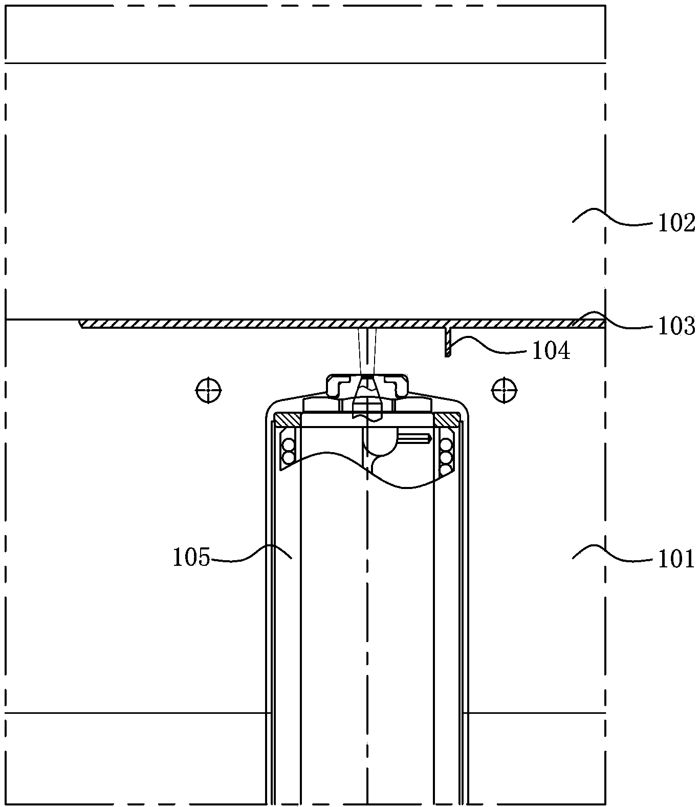
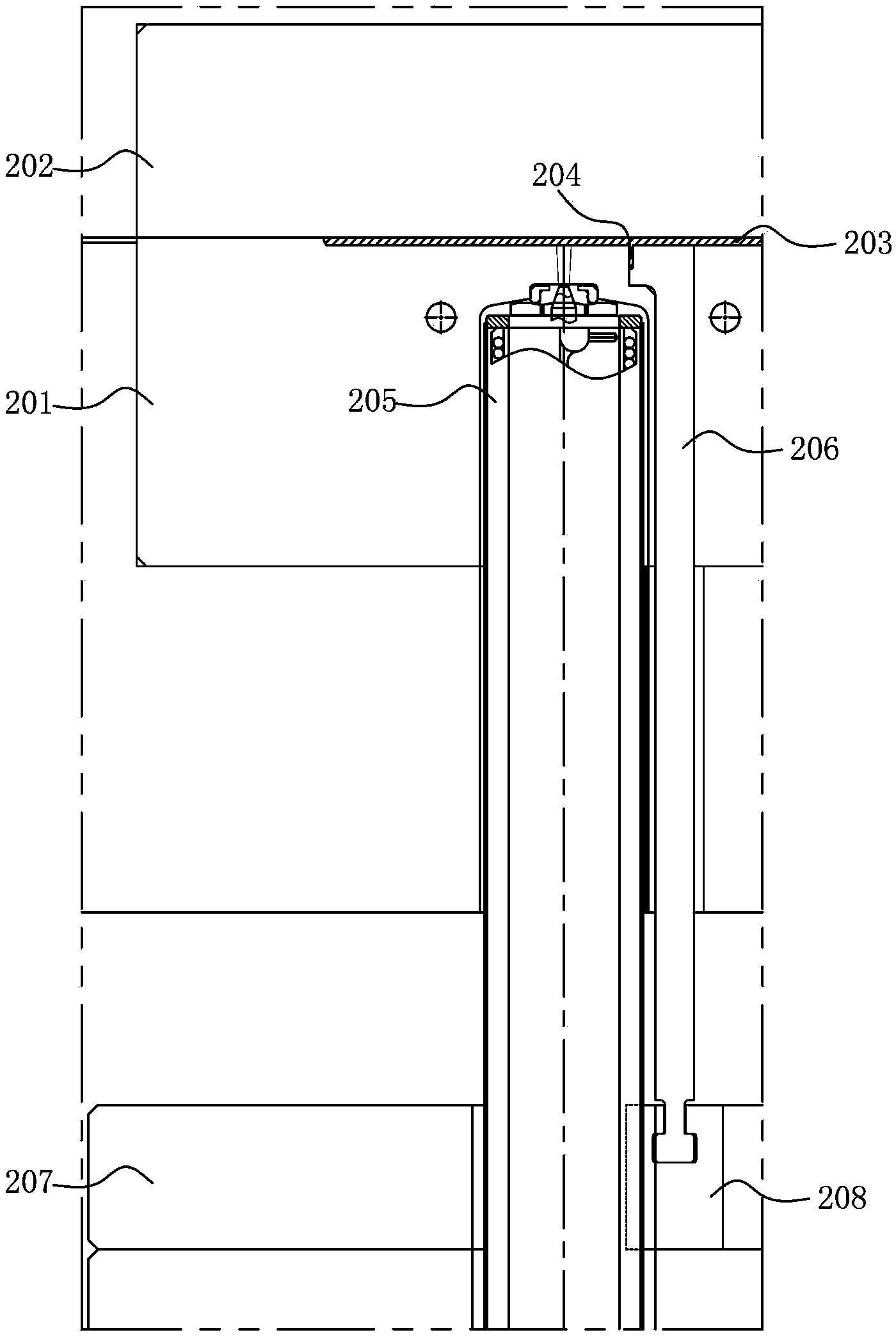
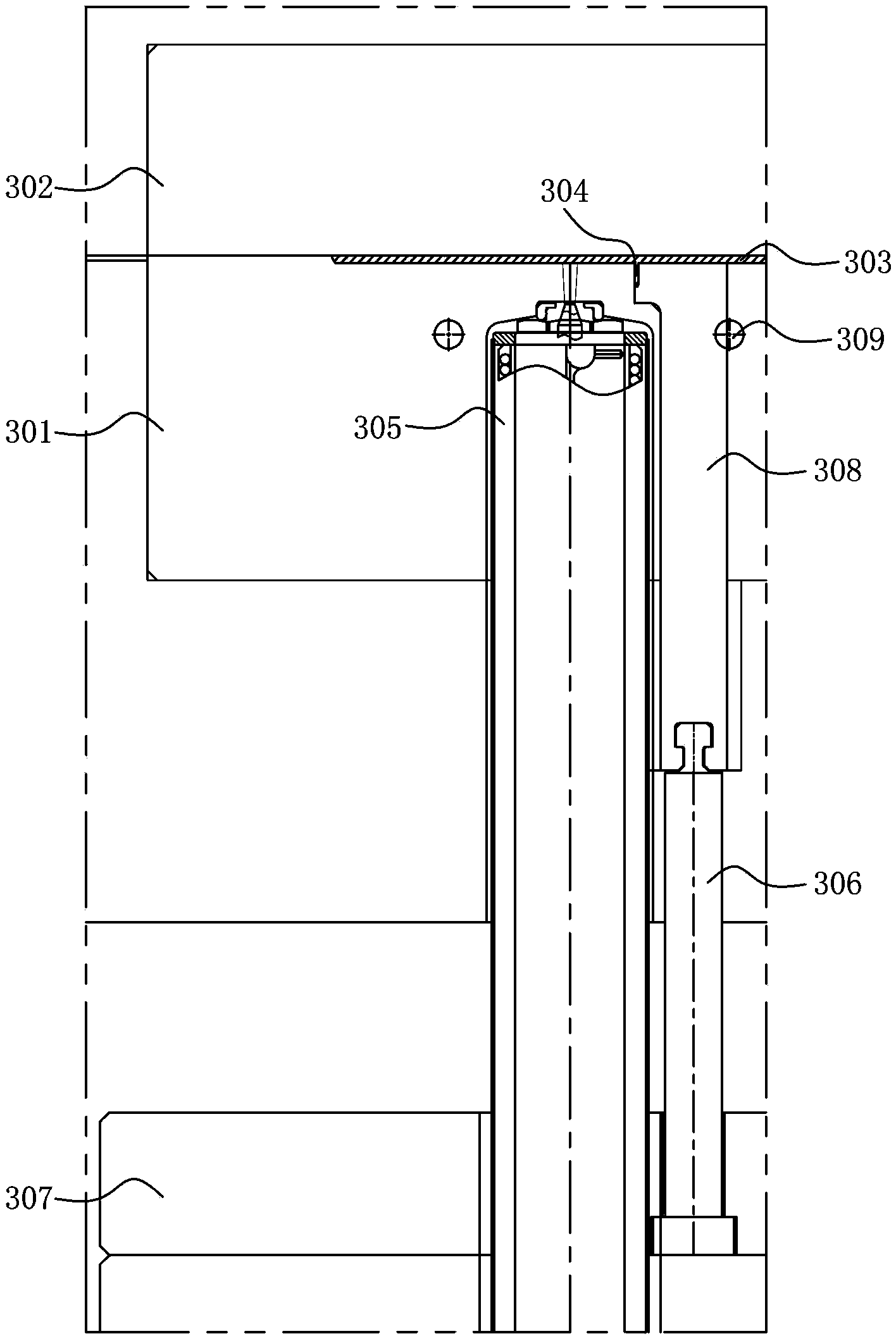
【Technical Field】 [0001] The invention relates to a rib ejection structure, in particular to a rib ejection structure above a hot glue lane. 【Background technique】 [0002] See figure 1 , figure 1 The drawing is a schematic diagram of the rib ejection structure above the first hot glue channel in the prior art. The male mold core 101 and the female mold core 102 of the mold are used to form a product 103. One side of the product 103 is provided with a rib 104. The male mold core 101 has a hot glue channel 105 therein. The upper position is the rib 104. The mold is provided with a thimble 106 on the product 103, the thimble 106 is set on the ejection plate 107, but because the rib 104 is provided above the hot glue path 105, the thimble 106 cannot be set directly on On or near the rib 104, it is still easy to cause a die when the die is opened. [0003] See again figure 2 , figure 2 The drawing is a schematic diagram of the rib ejection structure above the second hot glue lane ...

Claims


Application Information

Patent Timeline
Patent Type & Authority Applications(China)
IPC IPC(8): B29C45/40B29C45/74
CPCB29C45/332B29C45/2737B29C45/401
Inventor 郭文波曾桂桥
Owner MITAC PRECISION TECH(KUNSHAN) CORP
Learn More