Two-stage regeneration catalytic cracking method and device

A technology for catalytic cracking and regenerating catalysts, which is applied in catalytic cracking, cracking, petroleum industry, etc. It can solve the problems of affecting the coking effect, failing to reach the expected regenerator temperature, and affecting normal operation, so as to ensure the coking effect and reduce the The coke production rate of the device and the effect of improving the product yield

Inactive Publication Date: 2015-01-14
刘英聚
View PDF3 Cites 0 Cited by
  • Summary
  • Abstract
  • Description
  • Claims
  • Application Information

AI Technical Summary

Problems solved by technology

At present, the two-stage regeneration industrial device is set to take heat in the first stage of regeneration (the second stage of regeneration is not set to take heat), or is set to take heat in the second stage of regeneration (the first stage of regeneration is not set to take heat), the above two kinds The two-stage regeneration device cannot directly and simply apply the above-mentioned patented technology. If the above-mentioned patented technology is directly applied, the expected temperature of the regenerator (especially the regenerator without heat extraction) will not be reached, which will affect the burning effect and even affect the normal operation.

Method used


Image

  • Two-stage regeneration catalytic cracking method and device
  • Two-stage regeneration catalytic cracking method and device
  • Two-stage regeneration catalytic cracking method and device

Examples


Embodiment Construction

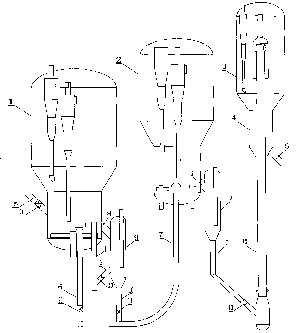
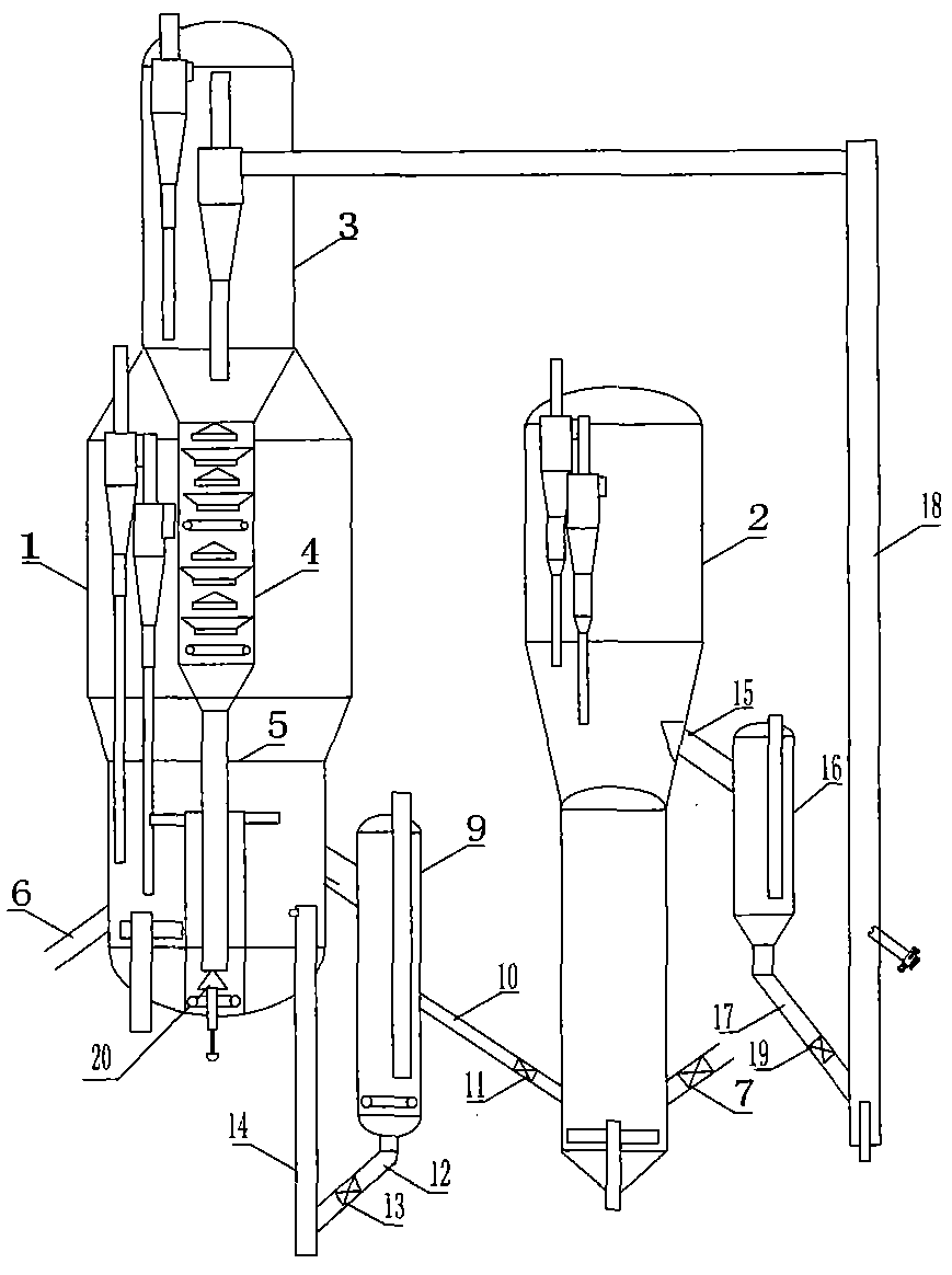
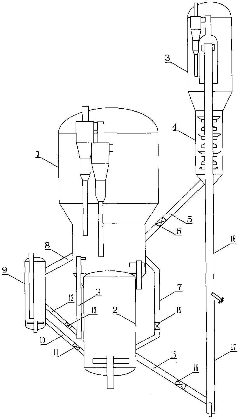
[0020] See figure 1 , 1 regenerator 1, 2 regenerator 2, and settler 3 are arranged side by side. The upper end of the stripping section 4 is connected to the lower end of the settler 3 , the lower part is connected to the upper end of the inclined tube 5 to be produced, and the lower end of the inclined tube 5 to be produced is connected to the regenerator 1 through the slide valve 21 to be produced. The upper part of the semi-regeneration standpipe 6 extends to the inside of the 1 regenerator 1, and the lower part is connected to the bottom of the semi-regeneration delivery pipe 7 through the semi-regeneration slide valve 20, and the upper end of the semi-regeneration delivery pipe 7 extends to the inside of the 2 regenerator 2. One end of the inlet pipe 8 of the combined external heat extractor is connected to the 1 regenerator 1, the other end is connected to the upper part of the combined external heat extractor 9, and the upper end of the exhaust pipe 10 is connected to t...


PUM


Abstract

The invention relates to a two-stage regeneration catalytic cracking method, belonging to the technical field of petrochemical industry and aiming at solving the problem that the traditional two-stage regeneration catalytic cracking is unsuitable for regulating solvent-oil ratio within a large range. The two-stage regeneration catalytic cracking method comprises the steps of reaction coking, catalyst deactivation and two-stage catalyst regeneration. The two-stage regeneration catalytic cracking method is characterized in that heat removal is set in two-stage regeneration processes; when the solvent-oil ratio is regulated within a large range, by regulating the heat removal of the two-stage regeneration, the invariable main air quantity of the two-stage regeneration can be realized, the temperature of the two-stage regeneration can be controlled to ensure the coking effect, and a regenerated catalyst with temperature of 620-700 DEG C is provided for a reaction process. The invention also provides a device for realizing the method. The device comprises a first regenerator, a second regenerator, a regenerant cooler and an outer combined heat removing device. The two-stage regeneration catalytic cracking method disclosed by the invention can be used for a heavy oil catalytic cracking device and can enhance the solvent-oil ratio of the device, reduce the coking rate of the device and increase the product yield.

Description

technical field [0001] The invention belongs to the technical field of petrochemical industry, in particular to a two-stage regenerative catalytic cracking method and device. Background technique [0002] The raw materials of heavy oil catalytic cracking units in the field of petrochemical industry are low-quality heavy oils with high carbon residues, high heavy metals, high viscosity, high colloids and asphaltenes. After decades of process research and practice, we know that to obtain ideal product distribution requires reasonable Technical conditions such as the carbon content of the regeneration agent, the ratio of agent to oil, good atomization of the raw material oil and good contact with the regeneration agent. In order to reduce the carbon content of the regenerant, the regenerator needs to be operated at a temperature of 690-700°C; in order to atomize the feedstock oil well, the preheating temperature of the feedstock oil is 200-250°C; when the above conditions are m...

Claims


Application Information

Patent Timeline
IPC IPC(8): C10G11/18
CPCC10G11/185
Inventor 刘英聚
Owner 刘英聚
Why Eureka
Try Eureka